Antitheft fingerprint coded lock

A combination lock and fingerprint technology, applied in the field of door locks, can solve the problems of short service life, user inconvenience, control system locking, etc., and achieve the effect of increasing the difficulty of unlocking, improving the anti-theft level, and increasing the protection strength.

Inactive Publication Date: 2016-06-29
CHENGDU PUTAISHENG TECH
View PDF6 Cites 1 Cited by
  • Summary
  • Abstract
  • Description
  • Claims
  • Application Information

AI Technical Summary

Problems solved by technology

[0003] At present, the fingerprint combination locks used at home and abroad are composed of a fingerprint module, an electronic lock body, and a controller separately installed outdoors, on the door body and indoors. Fingerprint image, digitize the fingerprint image through A / D conversion, and transmit the image data to the digital processor for image processing, identification, comparison, and then transmit the control signal to the motor-driven actuator in the electronic lock, but there are such defects , because the motor in the electronic lock body is the most prone to failure of the fingerprint combination lock, the shortcoming of the motor's short service life limits the service life of the fingerprint combination lock, and the controller circuit is also prone to failure, which affects the normal use of the fingerprint combination lock. As a result, the existing motor single-system fingerprint combination lock has a short service life, and once a failure occurs, it will cause inconvenience to the user
And, in the fingerprint password lock of the prior art, the input panel of password is directly exposed outside, often can cause its control system to lock because of young child or other unscrupulous person's constant attempt input, brings great inconvenience to the user. difficult to use

Method used


Image

  • Antitheft fingerprint coded lock
  • Antitheft fingerprint coded lock
  • Antitheft fingerprint coded lock

Examples


Embodiment 1

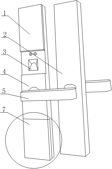
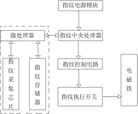
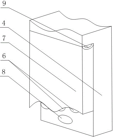
[0020] Such as Figure 1~Figure 3 As shown, this embodiment includes an indoor panel 2 and an outdoor panel 4, a fingerprint sensor panel 3 is installed on the top of the outdoor panel 4, a button panel 6 is installed on the bottom of the outdoor panel 4, and in the fingerprint sensor panel 3 A fingerprint power supply module, a fingerprint central processing unit, a fingerprint control circuit and a fingerprint collection module are provided, the output terminals of the fingerprint power supply module and the output terminal of the fingerprint collection module are respectively connected with the input terminals of the fingerprint central processing unit, and the output terminals of the fingerprint central processing unit It is connected with the fingerprint control circuit, and the fingerprint control circuit is connected with the fingerprint execution switch. A metal baffle 7 is installed on the lower part of the outdoor panel 4 through a torsion spring 9, and an electromagn...


PUM


Abstract

The invention discloses an antitheft fingerprint coded lock which comprises an indoor panel and an outdoor panel. A fingerprint induction panel is installed on the upper portion of the outdoor panel. A key panel is installed on the lower portion of the outdoor panel. A fingerprint power supply module, a fingerprint central processing unit, a fingerprint control circuit and a fingerprint collection module are arranged in the fingerprint induction panel. The output end of the fingerprint central processing unit is connected with the fingerprint control circuit. The fingerprint control circuit is connected with a fingerprint execution switch. A metal baffle is arranged on the lower portion of the outdoor panel through a torsional spring in a rotating mode. An electromagnet matched with the baffle is installed at the lower end of the key panel. The fingerprint execution switch is connected with the electromagnet. By means of two stages of antitheft protection, the protection strength of the key panel is increased, and in other words, lawbreakers can not directly input passwords on the key panel under the normal condition; therefore, it is ensured that the key panel can be started only through fingerprint identification, and therefore the maximum antitheft performance of the fingerprint coded lock is achieved.

Description

technical field [0001] The invention relates to the field of door locks, in particular to an anti-theft fingerprint combination lock. Background technique [0002] Fingerprint anti-theft lock is an intelligent lock, which is the perfect crystallization of computer information technology, electronic technology, mechanical technology and modern hardware technology. The characteristics of fingerprints have become the most important evidence for identification and are widely used in public security criminal investigation and judicial fields. Fingerprint authentication has the characteristics of convenience, speed and accuracy. [0003] At present, the fingerprint combination locks used at home and abroad are composed of a fingerprint module, an electronic lock body, and a controller separately installed outdoors, on the door body and indoors. Fingerprint image, digitize the fingerprint image through A / D conversion, and transmit the image data to the digital processor for image...

Claims


Application Information

Patent Timeline
Patent Type & Authority Applications(China)
IPC IPC(8): G07C9/00E05B9/00E05B49/00
CPCE05B9/002E05B49/00G07C9/37
Inventor 李奕廷
Owner CHENGDU PUTAISHENG TECH
Why Eureka
Try Eureka