Coil Component And Method Of Making The Same
A technology for coil components and components, which is applied in coil manufacturing, transformer/inductor components, transformer/inductor coils/windings/connections, etc., and can solve problems such as constant spacing, parasitic capacitance deviation characteristics, and deviations of difficult-to-wound wires. , to achieve the effect of reducing the deviation of parasitic capacitance and reducing the deviation of characteristics
- Summary
- Abstract
- Description
- Claims
- Application Information
AI Technical Summary
Problems solved by technology
Method used
Image

Examples
no. 1 approach
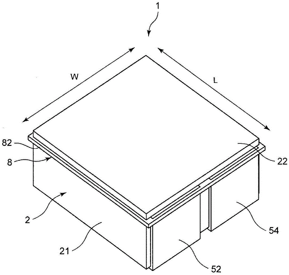
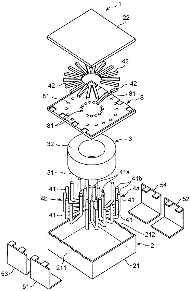
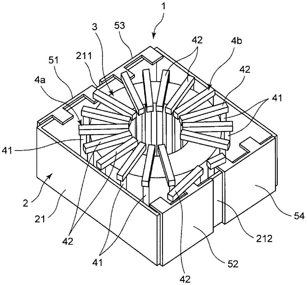
[0086] figure 1 It is a perspective view which shows the coil component of 1st Embodiment of this invention. figure 2 It is an exploded perspective view of the coil part. image 3 It is a perspective view omitting some coil components.
[0087] Such as figure 1 , figure 2 as well as image 3 As shown, the coil component 1 has a case 2, an iron core 3 arranged in the case 2, electrode terminals 51 to 54 mounted on the case 2, and primary coils wound around the iron core 3 and connected to the electrode terminals 51 to 54. side coil 4a and secondary side coil 4b. The coil component 1 functions as a choke coil or a transformer, for example.
[0088] The casing 2 is formed into a cube. The case 2 has a box-shaped bottom case 21 and a plate-shaped top case 22 , and the top case 22 is attached to the opening side of the bottom case 21 . The casing 2 is made of resin such as PPS or ceramics, for example.
[0089] The first electrode terminal 51 and the third electrode term...
no. 2 approach
[0120] Figure 6 It is a perspective view which shows the coil component of 2nd Embodiment of this invention. Figure 7 It is an exploded perspective view of the coil part. Figure 8 It is a plan view omitting some coil components. The coil component of the second embodiment differs from the coil component of the first embodiment in the mounting positions of the electrode terminals and the mounting state of the coil to the holding member.
[0121] Such as Figure 6 , Figure 7 as well as Figure 8 As shown, the coil component 1A has a case 2A, an iron core 3 disposed in the case 2A, electrode terminals 51 to 54 attached to the case 2A, and a primary coil wound around the iron core 3 and connected to the electrode terminals 51 to 54 . side coil 4a and secondary side coil 4b.
[0122] The casing 2A includes a box body 21A provided with an opening, and a cover body 22A attached to the opening of the box body 21A. Iron core 3 is housed in case 21A. Electrode terminals 51 t...
no. 3 approach
[0141] Figure 11 It is a perspective view which shows the coil component of 3rd Embodiment of this invention. The coil component of the third embodiment is different from the coil component of the second embodiment in that a second holding member is provided and an insulating tape is provided. This different structure will be described below.
[0142] Such as Figure 11 As shown, in the coil component 1B, in addition to the structure of the coil component 1A of the second embodiment, a second holding member 8B and an insulating tape 9 are provided. In addition, in the third embodiment, the same reference numerals as those in the second embodiment denote the same configurations as in the second embodiment, and therefore description thereof will be omitted.
[0143] The second holding member 8B is provided between the first end surface 31 of the iron core 3 and the coils 4 a and 4 b (first pin member 41 ) facing the first end surface 31 of the iron core 3 . The structure of...
PUM
 Abstract
Description
Claims
Application Information