Spiral grille dewatering machine

A technology of dehydrator and grid, which is applied in the direction of filtration and separation, membrane filter, fixed filter element filter, etc. It can solve the problems affecting the normal filtration of water, small filter seams, wear and other problems, and achieve high processing efficiency and space saving compact effect

Inactive Publication Date: 2016-07-06
AMCON FUJIAN ENVIRONMENT PROTECTION EQUIP CO LTD
View PDF5 Cites 1 Cited by
  • Summary
  • Abstract
  • Description
  • Claims
  • Application Information

AI Technical Summary

Problems solved by technology

Cause some sludge cannot move forward smoothly
When the screw shaft pushes the movable plate to swim, it will make the movable plate close to the front fixed plate, resulting in almost no gap near the outlet end, but the gap near the mud inlet end is too large, which will easily cause some sand or garbage to lock the filter seam live, it will also cause the filtrate to be not clean enough
If you come across some pasty materials, it will easily cause the filter seam between the fixed plate and the movable plate to be blocked, or you will encounter some materials that are not easy to filter. If the filter seam is too small, it will affect the water quality. normal filtration of
Also, since the movable plate is in contact with the screw shaft, there is wear between the two

Method used


Image

  • Spiral grille dewatering machine
  • Spiral grille dewatering machine
  • Spiral grille dewatering machine

Examples


no. 1 example

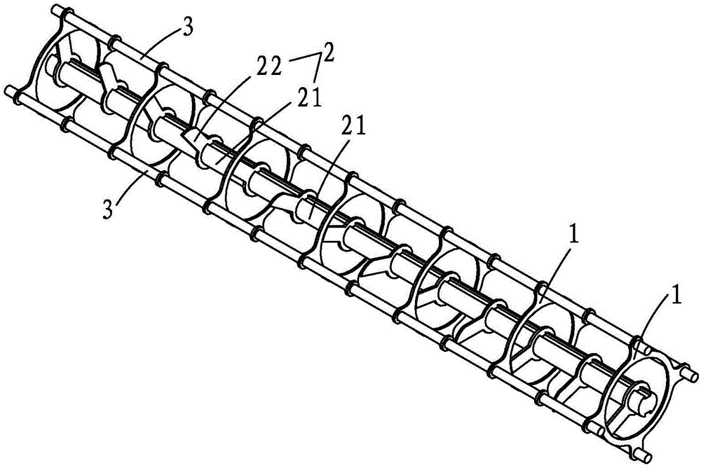
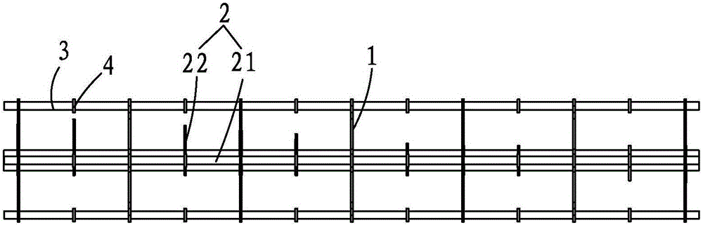
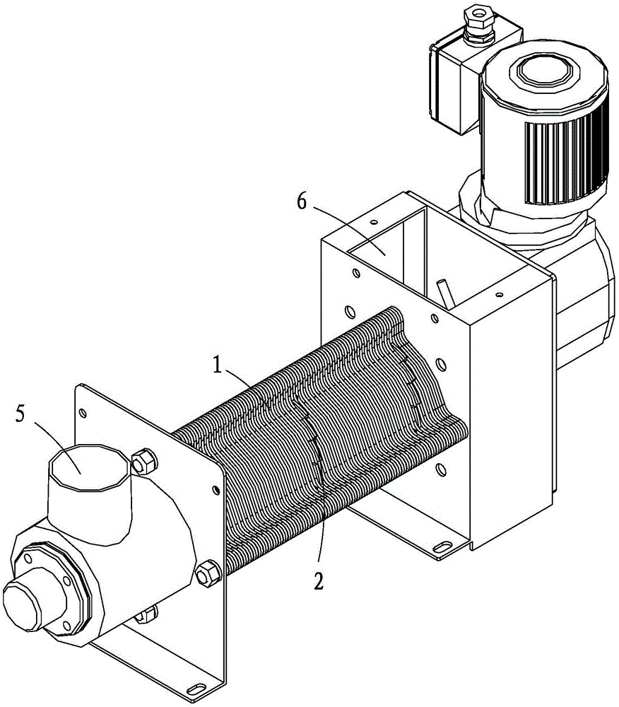
[0030] like Figure 1 to Figure 4 As shown, a spiral grill dehydrator includes a cavity formed by a plurality of adjacent fixed rings 1 and a screw shaft 2 passing through the cavity; the fixed ring 1 is circular, and the fixed ring The periphery of 1 is fixed by pillars 3, and spacers 4 are arranged on the pillars 3 to arrange the fixed rings 1 alternately and form filter seams; the spiral shaft 2 includes a central axis 21, a plurality of stacked rings perpendicular to the central axis The spiral blade formed by the shaft laminations 22; the shaft laminations 22 long-axis laminations at the corresponding positions of the filter seams formed between the fixed rings can be embedded and cleaned; the shaft laminations inside the stationary ring 1 It is a short-axis lamination, and its outer diameter is smaller than the inner diameter of the fixed ring 1.

[0031] The two ends of the cavity are respectively provided with a feed port 5 and a discharge port 6 . An adjustable back...

no. 2 example

[0034] like Figure 5 and Image 6 As shown, the fixed ring 1 is elliptical, and the shortest outer radius and the longest inner radius of the ellipse are equal; Slightly larger; the radius of the minor axis laminations 22 located in the fixed ring 1 is smaller than the shortest inner radius of the ellipse of the fixed ring 1 .

no. 3 example

[0036] like Figure 7 and Figure 8 As shown, the screw shaft is a double-ended intermittent screw shaft, and the fixed ring 1 has an inner protruding structure 11 at the position corresponding to the discontinuity of the double-ended intermittent screw shaft, such as Figure 9 As shown, the inner protruding structure 11 in the successively stacked retaining rings 1 forms a wiper shaft protrusion.

[0037] In addition, the structure of the shaft laminations 22 can be adjusted according to the materials to be processed and the functions to be realized, such as Figure 10 Shown is a structural schematic diagram of a shaft lamination of the present invention. like Figure 11 Shown is a structural schematic diagram of another shaft lamination of the present invention.

[0038] The advantages of the present invention are: 1. The integrated design of grid solid-liquid separation and solid conveying and extrusion has compact space. 2. For materials that are not easy to run out, ...


PUM


Abstract

The invention provides a spiral grille dewatering machine which comprises a cavity and a spiral shaft penetrating through the cavity.The cavity is formed by fixing rings stacked continuously or stacked at intervals.The peripheries of the fixing rings are fixed through supporting columns.Filter gaps are formed between the fixing rings stacked at intervals through partition parts on the supporting columns.The spiral shaft comprises a center shaft and a spiral blade perpendicular to the center shaft and formed by multiple stacked axial lamination sheets.The axial lamination sheets at the positions corresponding to the filter gaps formed between the fixing rings stacked at intervals are long axial lamination sheets and can be embedded into and clean the filter gaps.The axial lamination sheets at the positions corresponding to the fixing rings are short axial lamination sheets, and the outer diameter of the short axial lamination sheets is smaller than that of the fixing rings.The cavity is provided with a feed inlet and a discharge outlet.The spiral grille dewatering machine is compact in structure, provided with no quick-wear part and good in working effect.

Description

【Technical field】 [0001] The invention belongs to a solid-liquid separation device, in particular to a spiral grid dehydrator. 【Background technique】 [0002] Chinese invention patent 200780018706.9 discloses a stacked screw type solid-liquid separation device, which is equipped with solid-liquid separation parts of a plurality of adjacent fixed plates and a plurality of movable plates arranged between the adjacent fixed plates, and through The solid-liquid separation part extends at least one screw, and the movable plate is formed so that the rotating screw pushes the above-mentioned movable plate, and the object to be treated that enters the above-mentioned solid-liquid separation part is directed toward the solid by the rotating screw. The outlet of the liquid separation part is moved, and the filtrate separated from the object to be processed is discharged through the solid-liquid separation part of the solid-liquid separation part. [0003] The movable plate is driven ...

Claims


Application Information

Patent Timeline
Patent Type & Authority Applications(China)
IPC IPC(8): B01D29/44B01D29/64
CPCB01D29/445B01D29/64B01D2201/089
Inventor 郑朝志
Owner AMCON FUJIAN ENVIRONMENT PROTECTION EQUIP CO LTD
Why Eureka
Try Eureka