Pneumatic cam chuck clamping mechanism

A cam chuck and clamping mechanism technology, applied in the direction of the chuck, etc., can solve the problems of complex structure of the jaw driving mechanism, small movable jaw stroke, inconvenient use and maintenance, etc., and achieve simple and reliable structure, firm clamping, automatic The effect of high centering accuracy

Active Publication Date: 2016-07-06
JOUDER PRECISION INDAL KUSN
View PDF6 Cites 11 Cited by
  • Summary
  • Abstract
  • Description
  • Claims
  • Application Information

AI Technical Summary

Problems solved by technology

[0003] The existing ordinary three-jaw or four-jaw chucks are generally composed of three parts: the chuck body, the movable jaws and the jaw driving mechanism. In practical

Method used


Image

  • Pneumatic cam chuck clamping mechanism
  • Pneumatic cam chuck clamping mechanism
  • Pneumatic cam chuck clamping mechanism

Examples


Embodiment Construction

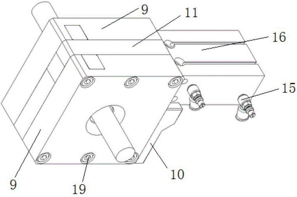
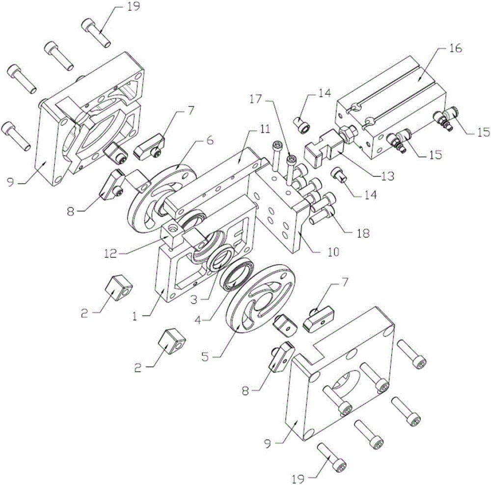
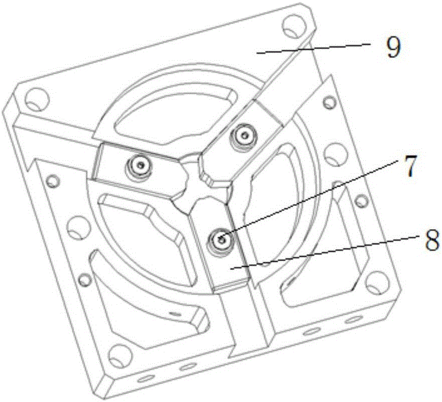
[0019] Such as Figure 1-Figure 5 As shown, a pneumatic cam chuck clamping mechanism includes a pneumatic assembly and a clamping body assembly. The overall structure of the clamping body assembly is square, and the pneumatic assembly is arranged on one side of the clamping body assembly. The pneumatic assembly includes a cylinder 16. The cylinder 16 is provided with a cylinder speed regulating valve 15 and an external pipeline. The clamping body assembly includes a chute plate 9 and a main body plate 1. The accommodation space is formed between the chute plate 9, the main body plate 1 and the splint 11. The cam The chuck is installed on the main body plate 1 through the ball bearing 4, and the high precision and low friction characteristics of the ball bearing 4 are used to ensure that the radial runout of the cam chuck is small during the rotation process, and the slider jaw 8 follows the cam through the cam. The actuator 7 is snapped into the cam chuck and can slide in the ...


PUM


Abstract

The invention discloses a pneumatic cam chuck clamping mechanism. A cylinder is provided with a cylinder speed regulating valve and an external pipeline, a clamping body component comprises a chute plate and a main body plate, the chute plate, the main body plate and the clamping plate form a containing space, a cam chuck is arranged on the main body plate by a ball bearing, and a slider clamping claw is clamped into the cam chuck by a cam following device and can slide in a corresponding chute in the chute plate. The pneumatic cam chuck clamping mechanism is provided and realizes the fast, bidirectional and automatic centering clamping particularly specific to round bar workpieces with the diameter below 20mm, a common cylinder is adopted as a driving unit, the pneumatic cam chuck clamping mechanism is simple and reliable in structure, convenient and fast to use, compact in structure, firm in clamping, good in workpiece perpendicularity and high in automatic centering precision.

Description

technical field [0001] The invention relates to a chuck type clamping mechanism, in particular to a pneumatic cam chuck clamping mechanism. Background technique [0002] In industrial production, there are a large number of spare parts that need to be processed with round bars. For the processing of this type of parts, the shape of the part's gyrator is often used, and various chuck fixtures are used as positioning and clamping tools. Chuck fixtures have the advantages of small size, automatic centering, and stable clamping, so they are widely used in industrial production. Ordinary chucks are machine tool accessories that use the radial movement of movable jaws evenly distributed on the chuck body to clamp and position the workpiece. [0003] The existing ordinary three-jaw or four-jaw chucks are generally composed of three parts: the chuck body, the movable jaws and the jaw driving mechanism. In practical applications, ordinary chucks have small strokes of the movable jaw...

Claims


Application Information

Patent Timeline
IPC IPC(8): B23B31/171
CPCB23B31/1612
Inventor 杨加华朱永保徐尊善
Owner JOUDER PRECISION INDAL KUSN
Why Eureka
Try Eureka