
Weighing and transporting device

A transportation device and weighing technology, which is applied in the direction of transportation and packaging, conveyor control devices, conveyors, etc., can solve problems such as inaccurate weighing data, center of gravity biased to one side, unstable center of gravity, etc.

Inactive Publication Date: 2016-07-06
SHENZHEN GENERAL MEASURE TECH
View PDF7 Cites 3 Cited by
  • Summary
  • Abstract
  • Description
  • Claims
  • Application Information

AI Technical Summary

Problems solved by technology

Because the conveying device often shakes during the process of conveying goods, and at the same time, the load cell in the existing conveying device is rigidly fixedly connected to the upper frame used to support the conveyor belt, which affects the measurement accuracy of the load cell, and at the same time The four load cells on the conveying device are fixed to each other, and the four load cells affect each other, resulting in inaccurate weighing data; at the same time, the motor in the existing conveying device is installed on the side of the pulley, so the overall center of gravity is biased towards one side, which makes the data collected by the data collection sensor inaccurate; due to the unstable center of gravity, the driving pulley has a large swing when conveying products, which reduces the service life of the conveying device

Method used


Image

  • Weighing and transporting device
  • Weighing and transporting device
  • Weighing and transporting device

Examples


no. 1 example

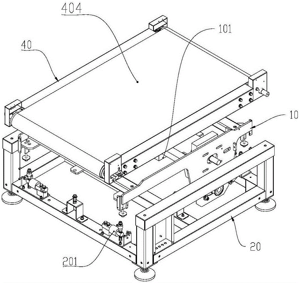
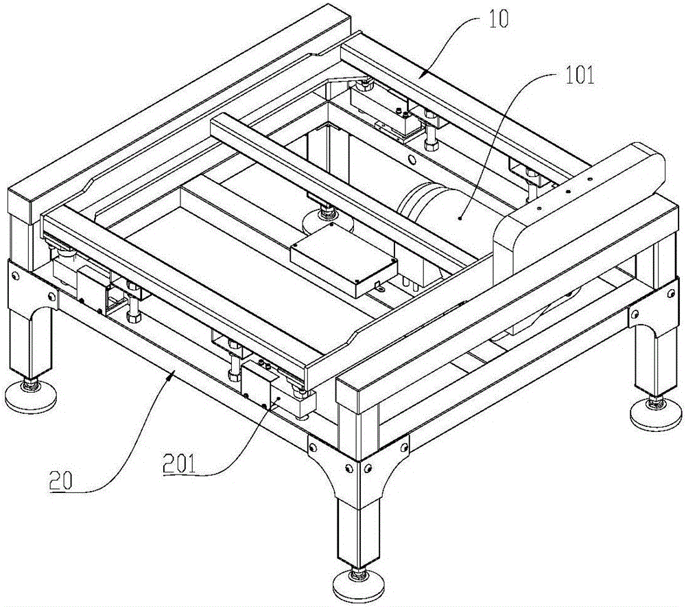
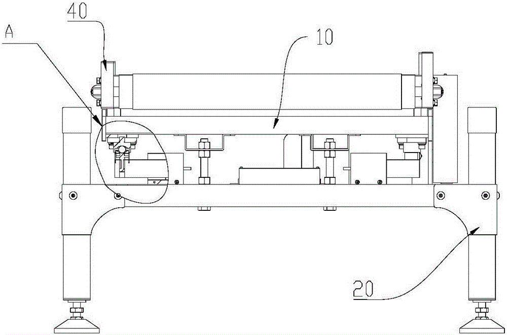
[0021] The first embodiment, such as Figure 1 to Figure 4 Shown, a kind of weighing and transporting device comprises top-level support 40, middle-level support 10 and bottom-level support 20 that are fixedly connected with top-level support 40; The driver 101 that drives the movement of the transmission belt 404, the bottom bracket 20 is fixed with a load cell 201 and an automatic centering assembly 30 fixedly connected with the load cell 201; the automatic centering assembly 30 includes a lower support column fixedly connected with the load cell 201 301, the upper support column 302 fixedly connected with the middle bracket and the steel ball 303 between the lower support column 301 and the upper support column 302; The upper receiving hole 305 of the steel ball 303 , the steel ball 303 is located in the lower receiving hole 304 and the upper receiving hole 305 and freely rotates in the lower receiving hole 304 and the upper receiving hole 305 .

[0022] Specifically, the ...

no. 2 example

[0025] The second embodiment, the difference between this embodiment and the first embodiment is that: the lower support column is provided with a second accommodation groove for accommodating the upper support column, and the bottom of the upper support column is sleeved in the second accommodation groove.

[0026] In other examples, such as Figure 5 with Image 6 As shown, the weighing transport device also includes a first roller assembly 70, a second roller assembly 50 and an adjustment assembly 60; the first roller assembly 70 and the second roller assembly 50 are connected by a transmission belt 404, and the top support 40 is provided with two parallel Side plate 401, one end of side plate 401 is respectively provided with horizontal chute 402, the other end of side plate 401 is provided with support hole 403, and first roller assembly 70 comprises first roller 703 and first roller shaft 701, the first roller shaft The two ends of 701 extend to the support holes 403 of...


PUM


Abstract

The invention discloses a weighing transportation device, which comprises a top bracket, a middle bracket and a bottom bracket; The connected automatic centering assembly; the automatic centering assembly includes the lower support column fixedly connected with the load cell, the upper support column fixedly connected with the middle bracket and the steel ball between the lower support column and the upper support column; the lower support column is set There are lower accommodation holes for accommodating steel balls, and the upper support column is provided with upper accommodating holes for accommodating steel balls. The steel balls are located in the lower accommodating holes and the upper accommodating holes and freely rotate in the lower accommodating holes and the upper accommodating holes. Its advantage is that the self-aligning component can effectively prevent the shaking of the bottom frame and reduce the error caused by shaking the data collected by the load cell; the driver is located at the center of gravity of the middle bracket, which reduces the impact on the data of the load cell due to the center of gravity being biased to one side collection.

Description

technical field [0001] The invention patent relates to a transportation device, especially a weighing transportation device. Background technique [0002] The conveying device is used to transport the goods, and in order to measure the weight of the conveyed goods during the process of conveying the goods, load cells are often installed on the conveying device to collect data, and then the weight of the goods is obtained according to the collected data. Because the conveying device often shakes during the process of conveying goods, and at the same time, the load cell in the existing conveying device is rigidly fixedly connected to the upper frame used to support the conveyor belt, which affects the measurement accuracy of the load cell, and at the same time The four load cells on the conveying device are fixed to each other, and the four load cells affect each other, resulting in inaccurate weighing data; at the same time, the motor in the existing conveying device is insta...

Claims


Application Information

Patent Timeline
Patent Type & Authority Applications(China)
IPC IPC(8): B65G41/00B65G43/08
CPCB65G41/001B65G43/08B65G2203/0258B65G2203/042
Inventor 尚学勇石红文周亮贺诗飞
Owner SHENZHEN GENERAL MEASURE TECH
Learn More