
Air Conditioning Controller Structure

An air-conditioning controller and controller technology, applied in mechanical equipment and other directions, can solve the problems of unreasonable structure, short service life, low disassembly and assembly efficiency, etc., and achieve the effects of high processing efficiency, long service life, and convenient disassembly and assembly.

Active Publication Date: 2019-12-17
QINGDAO HAIER AIR CONDITIONING ELECTRONICS CO LTD
View PDF7 Cites 0 Cited by
  • Summary
  • Abstract
  • Description
  • Claims
  • Application Information

AI Technical Summary

Problems solved by technology

The structure of the existing controller is simple and unreasonable; the operation is performed by buttons, the service life is short, the operation is inconvenient, and the user experience is poor; the components of the controller structure lack necessary connectors, and the disassembly efficiency is low and difficult. high scrap rate

Method used


Image

  • Air Conditioning Controller Structure
  • Air Conditioning Controller Structure
  • Air Conditioning Controller Structure

Examples


Embodiment 1

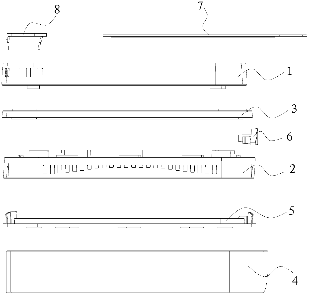
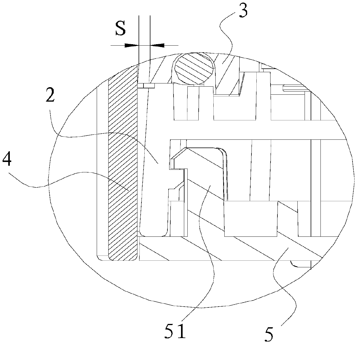
[0031] This preferred embodiment provides an air conditioner controller structure. Such as figure 1 As shown, the controller structure includes an upper shell 1 , a lower shell 2 , a touch screen and liquid crystal display assembly 7 and a Fresnel lens 8 . A light guide plate 3 is arranged between the upper case 1 and the lower case 2, and a decorative part 4 is arranged outside the light guide plate 3 and the lower case 2, and there is a gap S between the decorative part 4 and the light guide plate 3.

[0032] When the decorative part 4 is not installed, the side section of the controller is trapezoidal, with two base angles of 86°. The decorative part 4 is in the shape of a square, and after assembly, there will be a gap of 1.5 mm to 2.5 mm between the decorative part 4 and other parts of the controller, preferably 2 mm.

[0033] After electrification, the light emitted by the light guide plate 3 passes through the gap S, and is reflected by the decorative part 4 to pass t...

Embodiment 2

[0038] This preferred embodiment provides an air conditioner controller structure, which is basically the same as the first preferred embodiment. The controller structure includes an upper shell and a lower shell; a light guide plate is arranged between the upper shell and the lower shell, and a decorative part is arranged outside the light guide plate and the lower shell, and there is a gap S between the decorative part and the light guide plate. The light emitted by the light guide plate passes through the gap S, and is reflected by the decorative part to pass through the controller structure, forming an aperture outside the controller structure.

[0039] The difference is that the light guide plate can emit light of different colors according to the time and / or temperature, for example, it emits cool light in summer and warm light in winter; the specific shape of the decorative part is not limited, and it can be a word-shaped frame It can be in the shape of a groove, which ...


PUM


Abstract

The invention discloses an air conditioner controller structure and belongs to the field of controller hardware structures. The air conditioner controller structure is designed to solve the problems that an existing structure is inconvenient to use and uneasy to dismount and mount. The air conditioner controller structure comprises an upper shell and a lower shell. A light guide plate is arranged between the upper shell and the lower shell. A decorating piece is arranged outside the light guide plate and the lower shell. A gap S exists between the decorating piece and the light guide plate. Light emitted by the light guide plate transmits through the gap S, is reflected through the decorating piece and transmits out of the controller structure, and therefore a light circle is formed on the outer side of the controller structure. By the adoption of the air conditioner controller structure, the effect that a user can find a controller accurately and rapidly in darkness is guaranteed, using is more convenient, and the appearance is more attractive, cooler and more distinctive; dismounting and mounting are convenient, and the machining efficiency is high; and operation is more convenient and easy to learn, and the service life is long.

Description

technical field [0001] The invention relates to an air conditioner controller structure. Background technique [0002] The controller is an essential device for using the air conditioner. The structure of the existing controller is simple and unreasonable; the operation is performed by buttons, the service life is short, the operation is inconvenient, and the user experience is poor; the components of the controller structure lack necessary connectors, and the disassembly efficiency is low and difficult. High scrap rate. Contents of the invention [0003] One object of the present invention is to provide an air conditioner controller structure that is convenient to use and beautiful in appearance. [0004] Another object of the present invention is to provide an air conditioner controller structure with reasonable structure, convenient assembly and disassembly, and high processing efficiency. [0005] For reaching this purpose, the present invention adopts following tec...

Claims


Application Information

Patent Timeline
Patent Type & Authority Patents(China)
IPC IPC(8): F24F11/89
Inventor 王莉邓杨董德智国德防张中晓何敬芳
Owner QINGDAO HAIER AIR CONDITIONING ELECTRONICS CO LTD
Learn More