A Multilayer Electrode Displacement Sensor

A displacement sensor, multi-layer electrode technology, applied in the field of sensors, can solve the problems of flexible FPC deformation, terminal alignment difficulties, etc., to save costs, avoid alignment difficulties, and improve compactness.

Active Publication Date: 2019-01-11
UNITED PRECISION MACHINE
View PDF10 Cites 0 Cited by
  • Summary
  • Abstract
  • Description
  • Claims
  • Application Information

AI Technical Summary

Problems solved by technology

This scheme is very effective, FPC metallized small hole technology is mature, FPC and conductive glass substrate crimping technology is also mature, but the problem with this method is that the FPC that plays the role of leading out and conducting the grid electrodes on the glass substrate It needs to be expanded to a larger size than the glass substrate for preparing the grid electrode, and more space is needed; the bigger problem is that the flexible FPC that plays the role of leading the grid electrode on the glass substrate is easy to deform, and it needs to be deformed during the preparation of the circular electrode. For two-dimensional grid electrodes such as disks, it is very difficult to align the terminals on the flexible FPC with the terminals on the rigid glass substrate

Method used


Image

  • A Multilayer Electrode Displacement Sensor
  • A Multilayer Electrode Displacement Sensor
  • A Multilayer Electrode Displacement Sensor

Examples


specific Embodiment approach 1

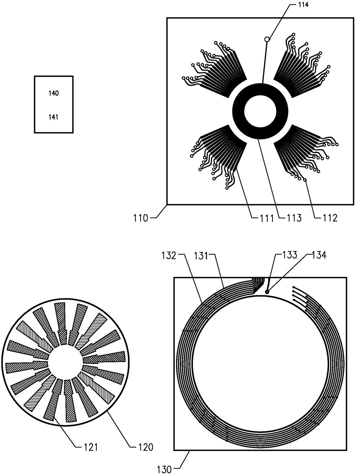
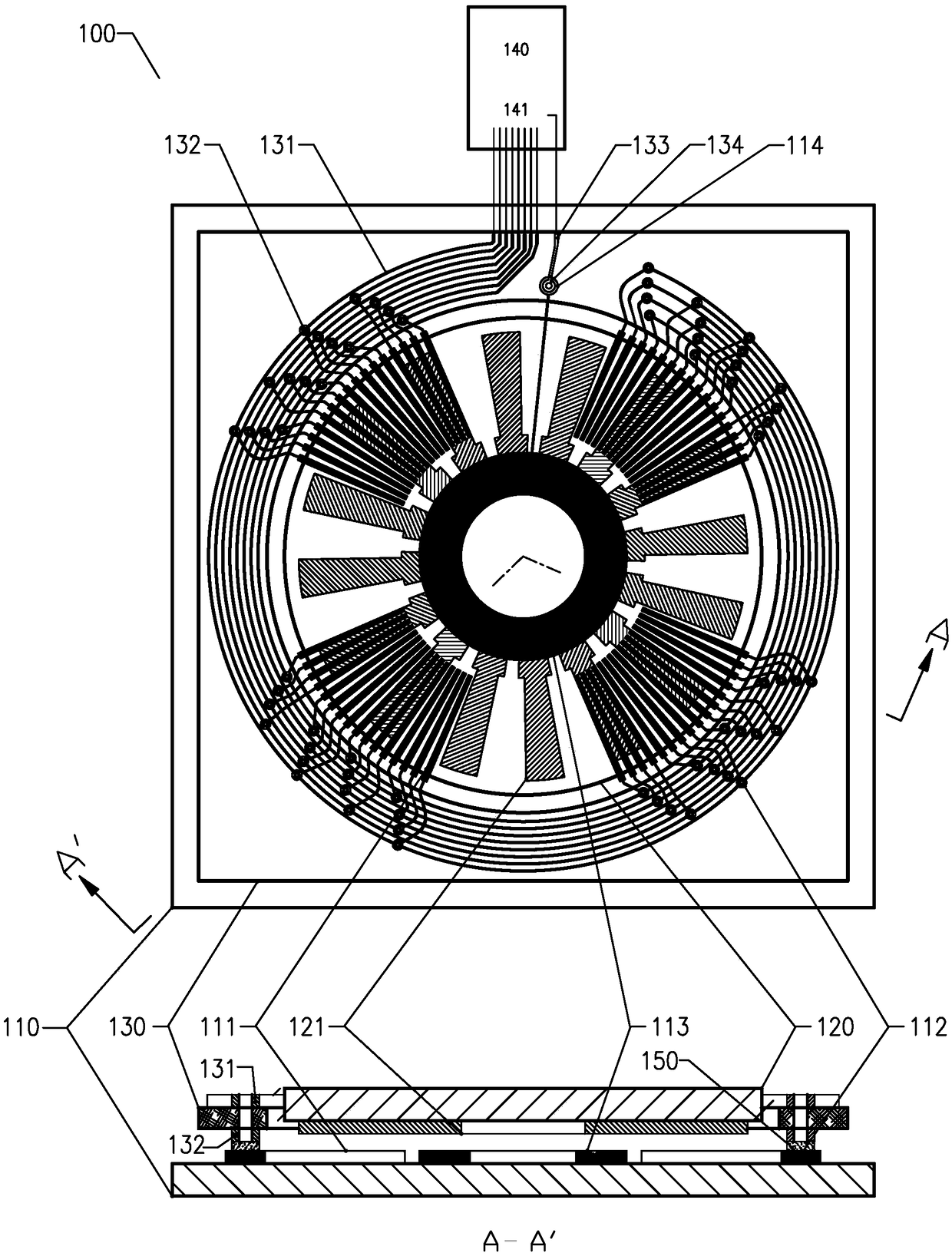
[0038] Such as Figure 1a and Figure 1b The capacitive grid angular displacement sensor 100 shown includes an emitter electrode substrate 110 , a coupling electrode substrate 120 , a wiring board 130 and a detection circuit 140 . The emitter electrode substrate 110 is a glass substrate, and the grid-shaped emitter electrode group 111 and the receiver electrode 113 are prepared on the same surface of the emitter electrode substrate 110, and each emitter electrode of the grid-like emitter electrode group 111 has an emitter electrode lead-out terminal , the outgoing terminals of each transmitting electrode form the transmitting electrode outgoing terminal group 112, and the receiving electrode 113 has a receiving electrode outgoing terminal 114; the coupling electrode substrate 120 is also a glass substrate, and the grid-shaped coupling electrode group 121 is prepared on the coupling electrode substrate 120, the coupling electrode group 121 transmits the electrical signal on the...

specific Embodiment approach 2

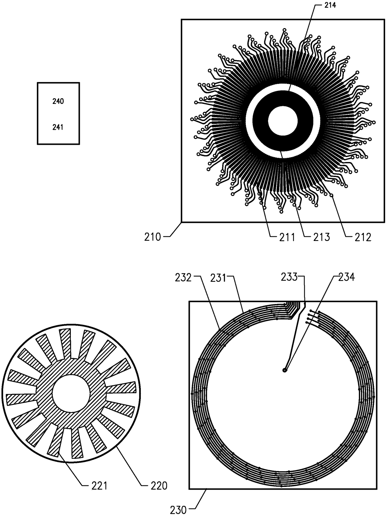
[0042] Such as Figure 2a and Figure 2b The capacitive grid angular displacement sensor 200 shown includes an emitter electrode substrate 210 , a coupling electrode substrate 220 , a wiring board 230 and a detection circuit 240 . The emitter electrode substrate 210 is a glass substrate, and the grid-shaped emitter electrode group 211 and the receiver electrode 213 are prepared on the same surface of the emitter electrode substrate 210, and each emitter electrode of the grid-like emitter electrode group 211 has an emitter electrode lead-out terminal position respectively. , the outgoing terminals of each transmitting electrode form the transmitting electrode outgoing terminal group 212, and the receiving electrode 213 has a receiving electrode outgoing terminal 214; the coupling electrode substrate 220 is also a glass substrate, and the gear-shaped coupling electrode 221 is prepared on the coupling electrode substrate 220 On, the coupling electrode 221 transmits the electrica...

specific Embodiment approach 3

[0046] Such as Figure 3a and Figure 3b The capacitive grid angular displacement sensor 300 shown includes an emitter electrode substrate 310 , a coupling electrode substrate 320 , a wiring board 330 and a detection circuit 340 . The emitter electrode substrate 310 is a ceramic material substrate, and the grid-shaped emitter electrode group 311 and the receiver electrode 313 are prepared on the same surface of the emitter electrode substrate 310, and each emitter electrode of the grid-like emitter electrode group 311 has an emitter electrode lead-out terminal position respectively. , the outgoing terminals of each transmitting electrode form the transmitting electrode outgoing terminal group 312, and the receiving electrode 313 has a receiving electrode outgoing terminal 314; the coupling electrode substrate 320 is also a ceramic material substrate, and the grid-shaped coupling electrode group 321 is prepared on the coupling electrode substrate 320, the coupling electrode gr...


PUM


Abstract

The invention discloses a multilayer electrode displacement sensor. According to the multilayer electrode displacement sensor, an emission electrode substrate is etched to form an emission electrode group of a grid-shaped electrode displacement sensor, a PCB is etched to form a grid-shaped emission leading-out electrode group, leading-out end positions of emission electrodes on the emission electrode substrate and conduction end portions of leading-out electrodes on the PCB respectively have same arrangement positions, the conduction end portions of the leading-out electrodes on the PCB are respectively aligned with the leading-out end positions of the emission electrodes on the emission electrode substrate in one-to-one correspondence, the conduction end portions of the leading-out electrodes on the PCB are respectively conducted with the leading-out end positions of the emission electrodes on the emission electrode substrate in one-to-one correspondence through a third-party conduction layer, so the emission electrodes on the glass substrate are respectively lead out to the PCB through the third-party conduction layer, the in-phase emission electrodes are mutually communicated through the multi-layer printed circuit board, and thereby the grid-shaped electrode displacement sensor is manufactured.

Description

technical field [0001] The invention relates to a sensor for measuring linear displacement and angular displacement, in particular to a capacitance grid displacement sensor and an inductance grid displacement sensor with grid electrodes. Background technique [0002] The grid electrode displacement sensor has the advantages of small size, low power consumption, and long-distance measurement, and has been widely used in displacement detection. The resolution of the grid electrode displacement sensor depends on the distance between adjacent grids. Taking the capacitance grid sensor as an example, the resolution of the usual 8-way drive phase detection type capacitance grid sensor is 0.01mm, the line spacing of adjacent emitter electrode grids is 0.635mm, the line width is 0.508mm, and the slit width is 0.127mm. There are 8 grids, and the actual sensor uses multiple sets of grids in parallel with a group spacing of 5.08mm to interconnect the electrodes of the same phase in eac...

Claims


Application Information

Patent Timeline
Patent Type & Authority Patents(China)
IPC IPC(8): G01B7/02G01B7/30
Inventor 陈其良陈赋康永忠陈梅英
Owner UNITED PRECISION MACHINE
Why Eureka
Try Eureka