A method for measuring the profile of an aeroengine blade

A technology of aero-engine, measurement method

Active Publication Date: 2018-03-16
CIVIL AVIATION FLIGHT UNIV OF CHINA
View PDF6 Cites 0 Cited by
  • Summary
  • Abstract
  • Description
  • Claims
  • Application Information

AI Technical Summary

Problems solved by technology

First, based on single-point high-precision measurement methods, such as the three-coordinate method, some studies use methods to improve the design of auxiliary measuring tools and measurement paths for measurement. This type of measurement method has high measurement accuracy, but its existing problems are: The measurement efficiency is low, the measurement cost is high, and all surface information cannot be obtained
However, the blade has special requirements. Although the fusion of marker points can obtain a certain amount of high-precision data, since marker points need to be attached to the surface of the measured object, this will inevitably have a certain impact on the data of the measured surface. Therefore, This technique is not suitable for the measurement of blades

Method used


Image

  • A method for measuring the profile of an aeroengine blade
  • A method for measuring the profile of an aeroengine blade
  • A method for measuring the profile of an aeroengine blade

Examples


Embodiment Construction

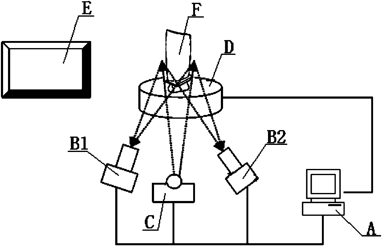
[0059] The present invention is a measurement method of aeroengine blade profile. First, the measurement method is based on a measurement system (disclosed prior art), see figure 1 As shown, the measurement system includes computer A, binocular industrial cameras (B1, B2), projector C, turntable D and positioning plane E. Among them, the computer A is used to control the action of the turntable D, the projector C and the binocular industrial camera (B1, B2), and the computer A is provided with a corresponding data processing program, and the measurement data collected by the scan is processed through the processing program. deal with. The projector C is used to project structured light onto the object to be measured on the turntable D-the blade F (that is, the blade of the aircraft engine). Binocular industrial cameras (B1, B2) are used to capture the deformed fringe pattern generated after the projector C is projected onto the measured object-the blade F. The positioning pla...


PUM


Abstract

The invention discloses an aviation engine blade profile measuring method. The measuring method is based on a measuring system. The measuring system comprises a computer, a binocular industrial camera, a projector, a turntable and a positioning plane. The measuring method comprises the steps of: calibrating the integral system; positioning the turntable with a positioning plane serving as a reference; fixing the blade on the turntable; projecting blue structured light to the measured blade by the projector; respectively capturing deforming stripes by the binocular industrial camera; performing phase resolving and matching and obtaining blade point cloud data of once measurement; automatically controlling the turntable by a program on the computer; repeating the projecting, capturing and solving processes, and obtaining 360-degree multi-view-angle measuring data of the blade; using a positioning quaternion and a rotating center to calculate the measured data; and automatically completing splicing of the blade profile and obtaining a complete fused data of the blade profile. The aviation engine blade profile measuring method has the advantages that the measuring precision is high and the measuring efficiency is high.

Description

Technical field [0001] The invention relates to a measuring technology of blade profile, in particular to a measuring method of aeroengine blade profile. Background technique [0002] The blade is the core component of an aero engine. The measurement technology of its profile profile is an important step in reverse engineering, quality inspection, blade design and maintenance guidance. Therefore, the measurement technology of aero engine blade profile has always been studied. Hot spot. [0003] Currently, measurement techniques for aero engine blades are usually divided into two categories. First, high-precision measurement methods based on single points, such as the three-coordinate method. Some studies use methods to improve the design of auxiliary measuring tools and measurement paths for measurement. This type of measurement method has high measurement accuracy, but its problems are: The measurement efficiency is low, the measurement cost is high, and all the surface informat...

Claims


Application Information

Patent Timeline
Patent Type & Authority Patents(China)
IPC IPC(8): G01B11/25G01B11/24
CPCG01B11/2433G01B11/2522
Inventor 魏永超黎新傅强赖安卿敖良忠王瀚艺赵伟
Owner CIVIL AVIATION FLIGHT UNIV OF CHINA
Why Eureka
Try Eureka