Eureka AIR delivers breakthrough ideas for toughest innovation challenges, trusted by R&D personnel around the world.

Method for identifying shearing force borne by elastic coupling based on strain

A technology of elastic coupling and identification method, applied in the direction of instruments, measuring force, measuring devices, etc., can solve the problems of lack of data support, insufficient measurement and calculation research, etc., and achieve convenient and fast use, high sensitivity, and rich verification technology. The effect of the indicator

Inactive Publication Date: 2016-07-06
SOUTHEAST UNIV
View PDF8 Cites 0 Cited by
  • Summary
  • Abstract
  • Description
  • Claims
  • Application Information

AI Technical Summary

Problems solved by technology

Therefore, it is also very important to detect the shear force of the elastic coupling during the working process. At present, there is no particularly reliable method to detect the shear force of the elastic coupling. It is very important for the design and evaluation of the elastic coupling. During the characteristic process of the ship, at present, the finite element calculation model is mostly used for calculation and analysis, and its correctness largely depends on the correctness of the model, its boundary conditions, and related parameters. At present, the parameters of ship elastic components The research on the measurement and calculation of the elastic coupling has not been carried out enough, and there is a lack of effective data support. Therefore, the measurement of its real force and vibration parameters will effectively enrich the design reference content of the elastic coupling.

Method used


Image

  • Method for identifying shearing force borne by elastic coupling based on strain
  • Method for identifying shearing force borne by elastic coupling based on strain
  • Method for identifying shearing force borne by elastic coupling based on strain

Examples


Embodiment Construction

[0029] The present invention will be further described below in conjunction with the accompanying drawings.

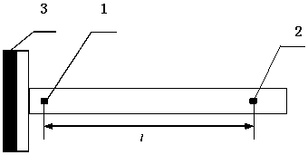
[0030] Such as figure 1 , figure 2 and image 3 Shown, concrete flow process of the present invention is:

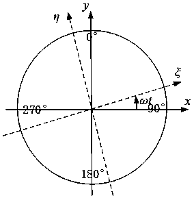
[0031] Step A: Select two sections on one side of the rotating shaft connected to the elastic coupling 3 as the measurement section, one of which is located close to the elastic coupling as the first measuring point 1, and the other measurement section is located away from the elastic coupling. The shaft joint is used as the second measuring point 2, and strain sensors and two sets of strain gauges perpendicular to each other are arranged on each measuring section, and the directions of the two sets of strain gauges are respectively marked as and direction.

[0032] Step B: Start the motor to turn the rotating shaft at low speed, use the strain sensor to measure and record the average strain of each measuring point in several cycles under the low-speed cr...


PUM


Abstract

The invention discloses a method for identifying a shearing force borne by an elastic coupling based on strain. The method includes the following steps that: step A, the directions of two groups of strain gauges are marked as a xi direction and an eta direction; step B, strain initial deviation values are calculated; step C, dynamic strain values are calculated; step D, the strain initial deviation values of each measure point are subtracted from the corresponding dynamic strain values of each measurement point, so that dynamic real strain values of each measurement point can be obtained; step E, dynamic bending moment values of corresponding measurement points are calculated; step F, a dynamic shearing force of the first measurement point in the xi direction and the eta direction is calculated; and step G, a dynamic shearing force under a fixed coordinate system xoy is calculated. The method of the invention has the advantages of simple operation and convenient use. The method has high measuring sensitivity. With the method adopted, detection on the shearing force borne by the elastic coupling can be realized through a strain method, check technical indicators of the elastic coupling can be enriched, and an accurate and powerful basis can be provided for the design and selection of elastic couplings.

Description

technical field [0001] The invention specifically relates to a method for identifying the shear force of an elastic coupling based on strain. Background technique [0002] The elastic coupling is a device used to adjust the torsional vibration characteristics of the transmission shaft system, compensate the axis displacement of the main and driven machines caused by vibration and impact, and continuously transmit torque and motion. It has high elasticity and certain damping. It can not only undertake power and motion transmission, but also take on the two important missions of buffering, vibration reduction and noise control. It also has stronger displacement compensation capability and service life. It is widely used in diesel engines. In the power plant and the transmission shaft system with large disturbance torque. [0003] In the development and application process of designing marine turbines, in addition to protecting the main and driven machines and improving the re...

Claims


Application Information

Patent Timeline
Patent Type & Authority Applications(China)
IPC IPC(8): G01L1/22
Inventor 房久正杨建刚
Owner SOUTHEAST UNIV
Why Eureka
Eureka Blog
Learn More