Combined type battery box

A battery box and combined technology, which is applied in the direction of battery pack parts, circuits, electrical components, etc., can solve the problems of increased manufacturing cost, inconvenience, scrapped battery pack, etc., and achieve the effect of low manufacturing cost and convenient installation

Active Publication Date: 2016-07-06
陈杰
View PDF6 Cites 15 Cited by
  • Summary
  • Abstract
  • Description
  • Claims
  • Application Information

AI Technical Summary

Problems solved by technology

[0004] 1. Once a battery is damaged, it is easy to cause the entire battery pack to be scrapped
[0005] 2. The fixing of the battery pack in the box is unreliable and inconvenient. During the high-altitude installation process, the battery pack is easy to slip or loosen
[0006] 3. The free space in the box is relatively large, resulting in an oversized box, which is not beautiful and affects installation
[0007] 4. Installed in different occasions, the capacity requirements of the battery pack are different. It is difficult for the traditional box to meet the requirements of different capacities, resulting in the need for too many box specifications and increased manufacturing costs.
If a larger box is used to install fewer batteries, it will not only cause waste of materials, but also make the box take up more space, affecting the overall installation of street lights

Method used


Image

  • Combined type battery box
  • Combined type battery box
  • Combined type battery box

Examples


Embodiment Construction

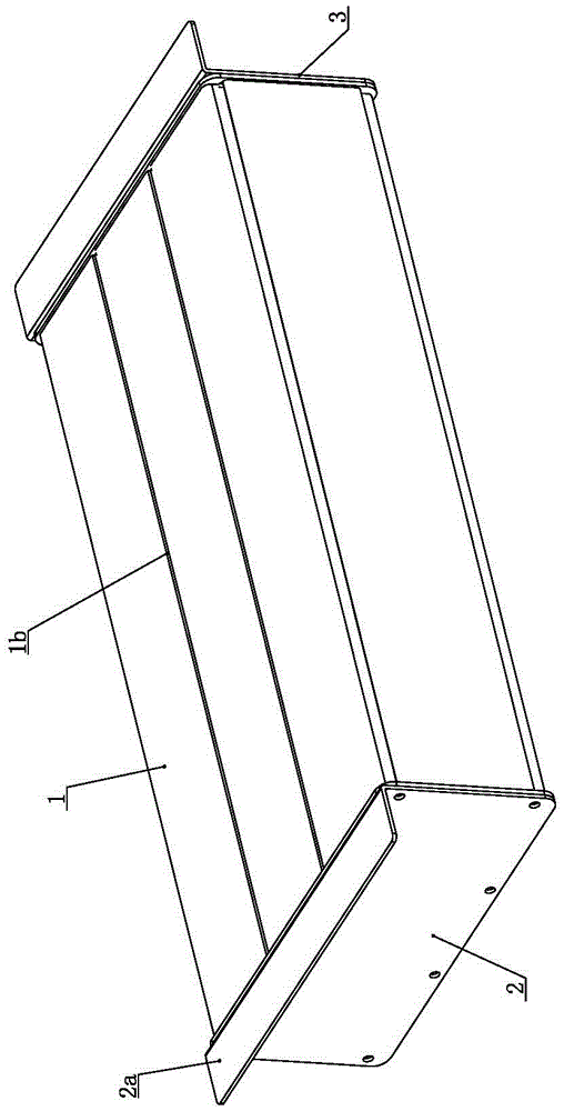
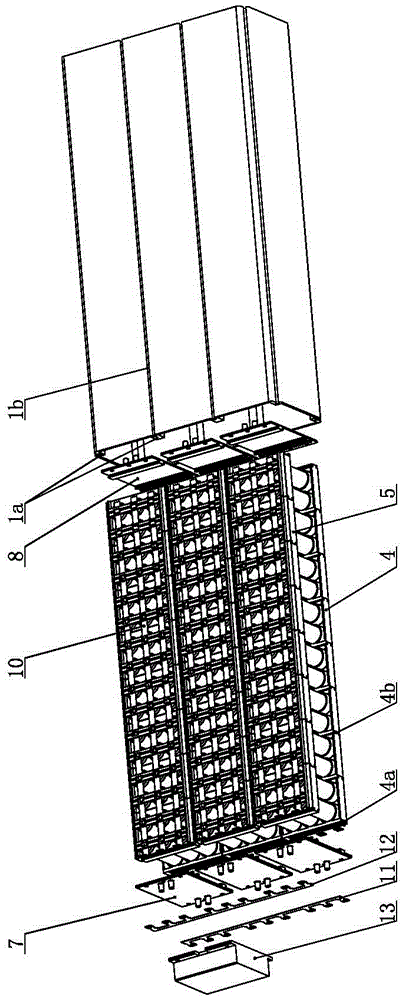
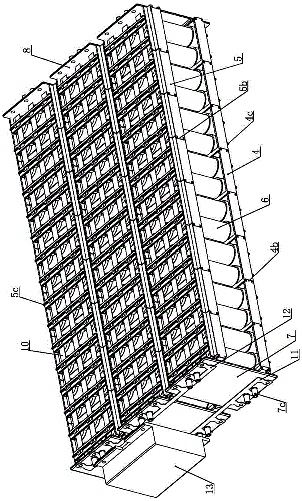
[0029] Such as Figure 1 to Figure 8 As shown, the combined battery box of the present invention includes a box body 1, and the box body 1 is a rectangular parallelepiped with two ends through. The outer sides of the convex ribs 1a are respectively provided with dovetail grooves 1b extending along the full length direction of the convex ribs, and the front and rear ends of the box body 1 are provided with a front end cover 2 and a rear end cover 3 which close the box body. Sealing rings are respectively provided between the end cover 3 and the end face of the box body 1, and the front end cover 2 and the rear end cover 3 are respectively fixed on the box body 1 by end cover screws, and the end cover screws are respectively screwed into the dovetail groove 1b, The inner cavity of the box body 1 is equipped with multiple rows of battery rows, and the four corners of each battery row are respectively clamped between the convex ribs 1a.

[0030]The cross-sectional shape of the bo...


PUM


Abstract

The invention discloses a combined type battery box. The box body is a cuboid with cut-through two ends, wherein multiple axial convex ribs are uniformly and symmetrically arranged on the top and the bottom of the box body; dovetail grooves extending along the full-length direction of the convex ribs are formed outside the convex ribs separately; a front end cover and a back end cover for sealing the box body are arranged at the front and back ends of the box body; sealing rings are arranged between the front end cover and the box body, and between the back end cover and the box body separately; the front and back end covers are fixed on the box body through end cover screws; the end cover screws are rotationally jointed in the dovetail grooves; multiple battery rows are mounted in the cavity of the box body; the four corners of each battery row are clamped among the convex ribs; each battery row is formed by multiple battery group units that are spliced from front to back in sequence; each battery group unit comprises a battery base and a battery top seat separately; multiple battery mounting holes are formed in the opposite end planes of the battery base and the battery top seat correspondingly; and a battery is mounted in each pair of the battery mounting holes separately. By adoption of the combined battery box, the batteries can be mounted and combined conveniently and rapidly, so that high space utilization ratio is realized.

Description

technical field [0001] The invention relates to a battery box for a solar street lamp, in particular to a combined battery box, which belongs to the technical field of energy storage batteries. Background technique [0002] With the advancement of technology and people's emphasis on energy saving and emission reduction, solar cell street lights have been more and more widely used. The usual way is to install the battery box under the solar panel, and the sunlight will shine on the solar panel during the day, and the electricity generated will charge the battery under the action of the battery controller. When lighting is needed at night, the battery controller will light up the LED Lamp head, powered by batteries. [0003] The traditional battery installation box is a cuboid cavity structure, the battery is installed in the inner cavity of the box, and the series or parallel connection between the batteries is formed by wire welding. Such a structure has the following disa...

Claims


Application Information

Patent Timeline
Patent Type & Authority Applications(China)
IPC IPC(8): H01M2/10H01M50/20H01M50/204
CPCH01M50/20Y02E60/10
Inventor 陈杰
Owner 陈杰
Why Eureka
Try Eureka