Antenna tuning method and antenna tuning device

A technology for antenna tuning and tuning networks, which is applied in the field of communication, and can solve problems such as excessive standing waves, inability to tune antennas, and real-time changes

Active Publication Date: 2016-07-06
NUBIA TECHNOLOGY CO LTD
View PDF3 Cites 15 Cited by
  • Summary
  • Abstract
  • Description
  • Claims
  • Application Information

AI Technical Summary

Problems solved by technology

[0004] The main purpose of the present invention is to propose an antenna tuning method, circuit and device, aiming to sol

Method used


Image

  • Antenna tuning method and antenna tuning device
  • Antenna tuning method and antenna tuning device
  • Antenna tuning method and antenna tuning device

Examples


Embodiment 1

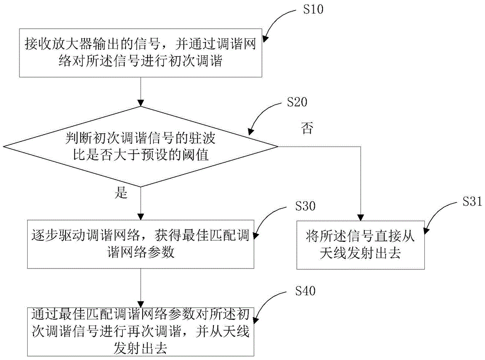
[0083] Such as image 3 As shown, the first embodiment of the present invention proposes an antenna tuning method, the method includes steps:

[0084] S10. Receive a signal output by the amplifier, and perform initial tuning on the signal through a tuning network;

[0085] S20. Determine whether the standing wave ratio of the initial tuning signal is greater than a preset threshold;

[0086] S30. If so, gradually drive the tuning network to obtain the best matching tuning network parameters; otherwise, enter step S31 and directly transmit the signal from the antenna;

[0087] S40. Perform retuning on the primary tuning signal by best matching the tuning network parameters, and transmit it from the antenna.

[0088] In this embodiment, the standing wave is intelligently detected and the tuning network is optimally matched, so that the standing wave ratio is smaller and more energy is radiated through the antenna.

[0089] In this embodiment, the signal to be sent is first am...

Embodiment 2

[0092] Such as Figure 4 As shown, in this embodiment, step S20 includes:

[0093] S21. Perform standing wave detection on the initial tuning signal in real time or at regular intervals;

[0094] S22. Calculate the standing wave ratio of the standing wave through the CPU operation unit;

[0095] S23. Compare the standing wave ratio with a preset threshold.

[0096] In this embodiment, the calculation of the standing wave ratio of the standing wave by the CPU operation unit includes:

[0097] coupling a reflected power coupling signal and an incident power coupling signal from the initial tuning signal through a bidirectional coupler;

[0098] Collect the reflected voltage value of the reflected power coupling signal through the first detection circuit connected in sequence, the first low-pass filter and the first DC acquisition module; through the second detection circuit connected in sequence, the second low-pass filter and the second The DC acquisition module acquires th...

Embodiment 3

[0101] Such as Figure 5 As shown, the present invention further provides an antenna tuning circuit, including:

[0102] Amplifier PA, used to amplify the input signal and output it to the tuning network to be tuned into the initial tuning signal;

[0103] A detection circuit for judging whether the standing wave ratio of the initial tuning signal is greater than a preset threshold; if so, gradually driving the tuning network to obtain the best matching tuning network parameters;

[0104] The tuning network is used to initially tune the signal output by the amplifier, and to re-tune the initial tuning signal by best matching the parameters of the tuning network.

[0105] In this embodiment, the detection circuit includes: a bidirectional coupler, a first detection circuit connected in sequence, a first low-pass filter LPF1 and a first DC acquisition module AD1, a second detection circuit connected in sequence, a second Low-pass filter LPF2 and second DC acquisition module AD...


PUM


Abstract

The invention discloses an antenna tuning method, an antenna tuning circuit and an antenna tuning device, and belongs to the technical field of communication. The method comprises the following steps: receiving a signal output by an amplifier, and tuning the signal preliminarily through a tuning network; judging whether the standing wave ratio of the preliminarily-tuned signal is greater than a preset threshold; if the standing wave ratio of the preliminarily-tuned signal is greater than the preset threshold, gradually driving the tuning network to get the best matching tuning network parameters; and secondarily tuning the preliminarily-tuned signal based on the best matching tuning network parameters, and sending the signal out through an antenna. By detecting standing wave intelligently and matching the tuning network to the best, the standing wave ratio is smaller, and more energy is radiated out through the antenna.

Description

technical field [0001] The present invention relates to the field of communication technologies, in particular to an antenna tuning method and device. Background technique [0002] In the antenna transceiver circuit of the communication system, the standing wave is often too large due to the impedance matching problem, so that the signal passed through the amplifier cannot be completely transmitted through the antenna, and the reflected energy will also damage the components in the circuit. Even cause the system to fail to work. In the existing technical solutions, the RF circuit part of many electronic terminal equipment often measures the parameters of its load impedance and standing wave through instruments, and then improves the impedance parameters on the hardware to make the impedance more matching, so as to reduce the impact of reflected signals on the circuit. Impact. [0003] However, manually modifying the hardware matching parameters is too cumbersome during the...

Claims


Application Information

Patent Timeline
IPC IPC(8): H04B1/04H04B1/18H04B17/10H04B17/12H04B17/21
CPCH04B1/0458H04B1/18H04B17/102H04B17/103H04B17/12H04B17/21H04B1/04H04B17/10
Inventor 曾蓁
Owner NUBIA TECHNOLOGY CO LTD
Why Eureka
Try Eureka