Electronic equipment and manufacturing method for metal shell of electronic equipment

A technology for metal shells and electronic equipment, applied in the direction of metal shells, etc., can solve the problem of single visual effect of metal shells, and achieve the effects of rich visual effects, improved user experience, and enhanced aesthetics.

Inactive Publication Date: 2016-07-06
LENOVO (BEIJING) CO LTD
View PDF7 Cites 3 Cited by
  • Summary
  • Abstract
  • Description
  • Claims
  • Application Information

AI Technical Summary

Problems solved by technology

[0004] This application provides an electronic device, which is used to solve the

Method used


Image

  • Electronic equipment and manufacturing method for metal shell of electronic equipment
  • Electronic equipment and manufacturing method for metal shell of electronic equipment
  • Electronic equipment and manufacturing method for metal shell of electronic equipment

Examples


Example Embodiment

[0041] In order to make the objectives, technical solutions, and advantages of the present invention clearer, the following will clearly and completely describe the technical solutions in the embodiments of the present invention with reference to the accompanying drawings in the embodiments of the present invention. Obviously, the described embodiments are only It is a part of the embodiments of the present invention, not all the embodiments. Based on the embodiments of the present invention, all other embodiments obtained by those of ordinary skill in the art without creative work shall fall within the protection scope of the present invention. In the case of no conflict, the embodiments of the present invention and the features in the embodiments can be combined with each other arbitrarily. And, although a logical sequence is shown in the flowchart, in some cases, the steps shown or described may be performed in a different order than here.

[0042] Optionally, in the embodime...


PUM


Abstract

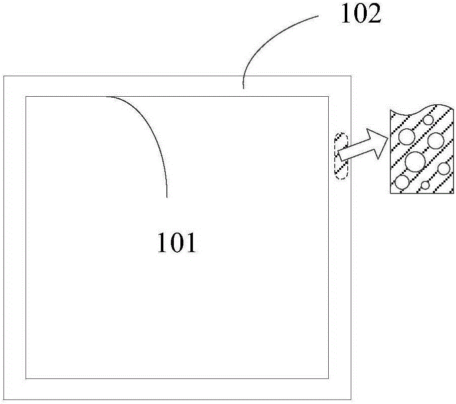
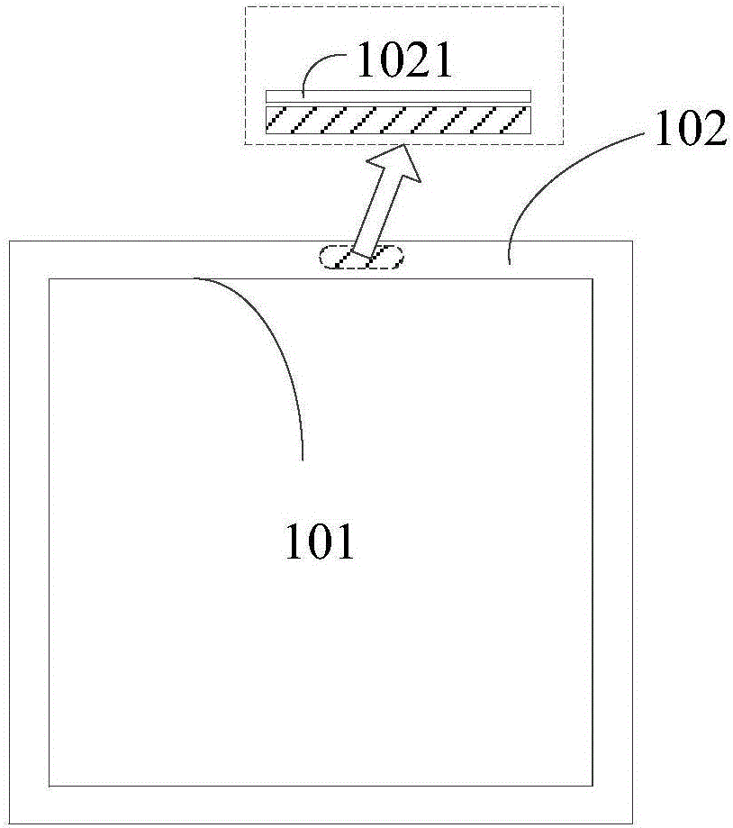
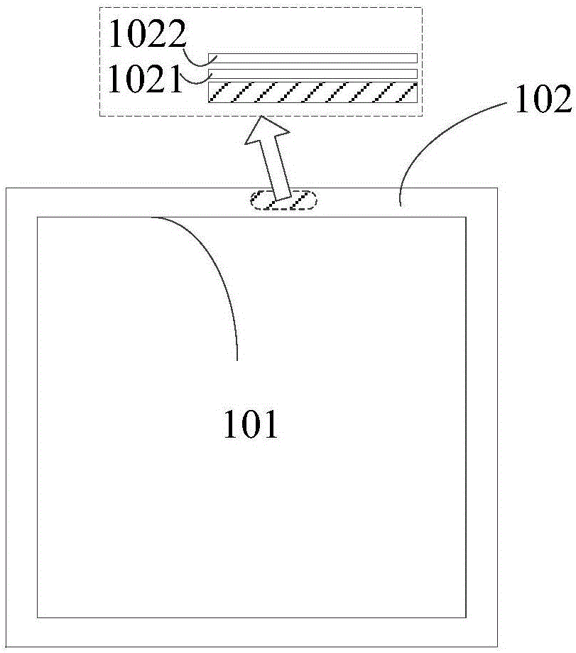
The invention discloses electronic equipment used for solving the technical problem of a single visual effect of the metal shell. The electronic equipment comprises a main body, and a shell, wherein the main body comprises electronic components and parts and a mounting body for mounting the electronic components and parts; the shell is connected with the main body; the shell satisfies a predetermined shape; the predetermined shape is matched with the main body, wherein the shell is made from a metallic material; a metal fluff appearance effect is formed on the outer surface of the shell; and the metal fluff appearance effect is formed by reflection of external light rays by multiple nano-scale micropores in the outer surface of the shell. The invention also discloses a manufacturing method for the metal shell of the corresponding electronic equipment.

Description

technical field [0001] The invention relates to the field of equipment manufacturing, in particular to an electronic equipment and a method for manufacturing a metal casing of the electronic equipment. Background technique [0002] At present, the appearance of electronic equipment is mainly displayed to users through the casing of the electronic equipment. In the prior art, the casings of electronic equipment are mostly made of metal materials. In order to make these metal casings produce different appearance effects, a common The method is generally spraying or wire drawing. Therefore, the appearance effect of the metal casing in the prior art is basically sprayed with different colors or drawn into different textures, resulting in a relatively single visual effect of the metal casing. [0003] It can be seen that there is a technical problem in the prior art that the visual effect of the metal shell is relatively simple. Contents of the invention [0004] The present ...

Claims


Application Information

Patent Timeline
IPC IPC(8): H05K5/04C23F1/20
CPCH05K5/04C23F1/20
Inventor 周文荣
Owner LENOVO (BEIJING) CO LTD
Why Eureka
Try Eureka