Water way system of instantaneous water dispenser

A waterway system and water dispenser technology, which is applied in beverage preparation devices, household appliances, applications, etc., can solve the problem of small hot water outlet flow, and achieve the effect of increasing water output and improving heating efficiency

Inactive Publication Date: 2016-07-13
边江
View PDF5 Cites 2 Cited by
  • Summary
  • Abstract
  • Description
  • Claims
  • Application Information

AI Technical Summary

Problems solved by technology

It solves the problem of small hot water flow in existing instant hot water dispensers

Method used


Image

  • Water way system of instantaneous water dispenser
  • Water way system of instantaneous water dispenser
  • Water way system of instantaneous water dispenser

Examples


Embodiment 1

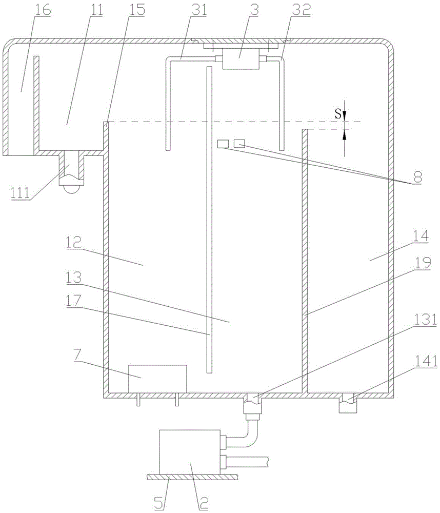
[0034] Such as figure 1 Shown: the waterway system of instant hot water dispenser, including balance water tank, water pump A2 and water pump B3.

[0035] A water outlet bin 11, a heating bin 12, a water inlet bin 13 and a drain bin 14 are provided in the balance water tank. The bottom of the water outlet bin 11 is provided with a water outlet 111, the bottom of the water inlet bin 13 is provided with a water inlet 131, and the bottom of the drainage bin 14 is provided with a drain outlet 141.

[0036] The water outlet bin 11, the heating bin 12, the water inlet bin 13 and the drain bin 14 are all under the same atmospheric pressure. Specifically, the water outlet bin 11, the heating bin 12, the water inlet bin 13 and the drain bin 14 are connected to each other through the gaps between their respective cavity walls and the top surface of the balance water tank at the upper ends. The balance water tank is also provided with an exhaust chamber 16 The upper end of the exhaust chambe...

Embodiment 2

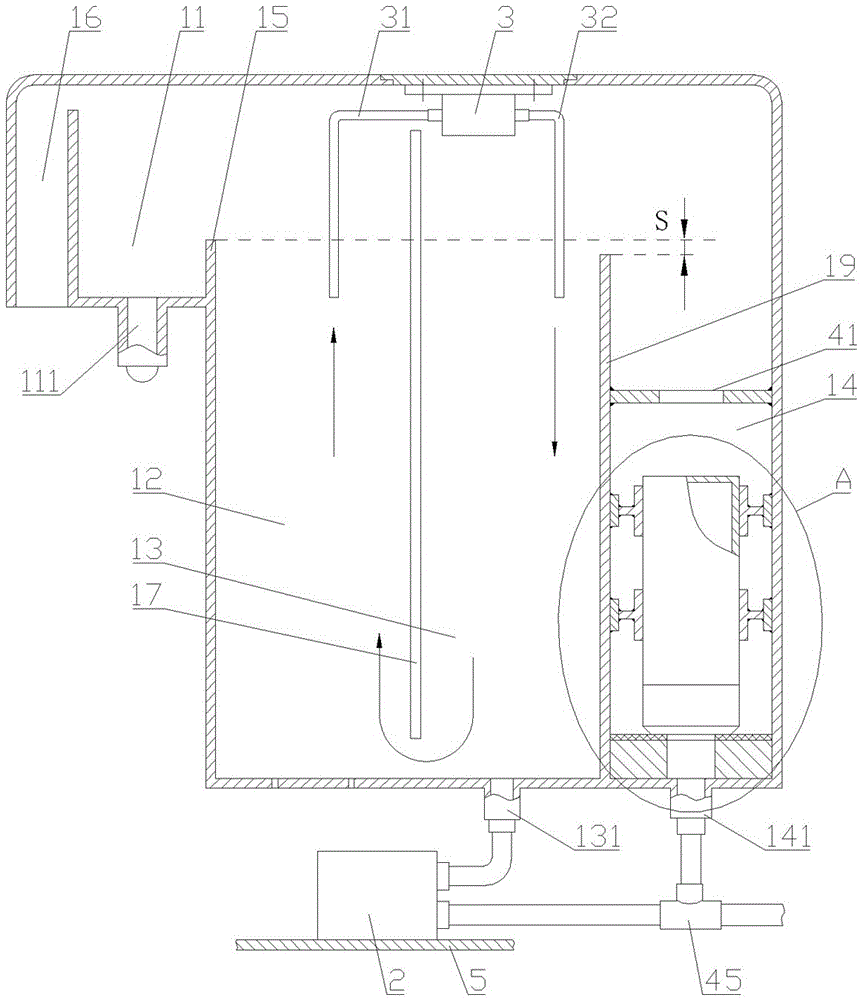
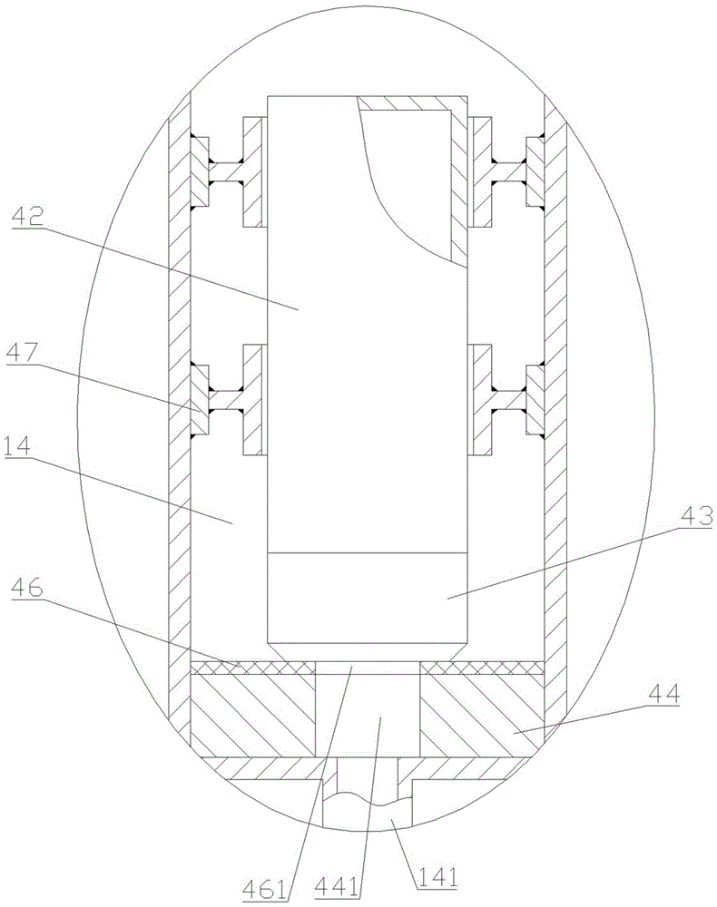
[0043] Such as figure 2 , 3 As shown, the difference between this embodiment and Embodiment 1 is only that it also includes a residual water return mechanism, which includes a float 42, a counterweight 43, a sealing platform 44 and a three-way joint 45. The buoy 42 is set in the drainage bin 14 and floats or sinks under the buoyancy of water. The counterweight 43 is connected to the lower end of the buoy 42. The sealing platform 44 is located at the bottom of the drainage bin 14, and the sealing platform 44 is provided with drainage The position of the drainage port 141 of the silo 14 corresponds to the water leakage hole A441; when there is no water in the drainage silo 14, the counterweight 43 presses the sealing platform 44 under the action of gravity, and then closes the drain 141 of the drainage silo 14 and the three-way joint 45 The first end is connected to the drain port 141 of the drainage bin through a pipe, the second end is connected to the water inlet end of the wa...


PUM


Abstract

The invention provides a water way system of an instantaneous water dispenser.The water way system comprises a balance water tank, a water pump A and a water pump B.A water outflow bin, a heating bin, a water inflow bin and a water drainage bin are arranged in the balance water tank.A water outlet is formed in the lower portion of the water outflow bin, a water inlet is formed in the lower portion of the water inflow bin, the water inlet is directly communicated with the interior of the water inflow bin, and a water drainage opening is formed in the lower portion of the water drainage bin.The water outflow bin, the heating bin, the water inflow bin and the water drainage bin are all located at the same barometric pressure.The lower end of the heating bin and the lower end of the water inflow bin are communicated.Water overflowing when the highest water level of the water inflow bin is achieved flows into the water drainage bin.The water in the heating bin is boiled and turned over to go over the side wall of the heating bin to enter the water outflow bin.The water outflow end of the water pump A is communicated with the water inlet, the water inflow end is communicated with a water source, one end of the water pump B is communicated with the interior of the heating bin through a pipeline A, and the other end of the water pump B is communicated with the interior of the water inflow bin through a pipeline B.On the premise that the power of the electric heater is not improved, the heating efficiency of the instantaneous water dispenser is improved, and the effluent amount of the instantaneous water dispenser is increased.

Description

Technical field [0001] The invention relates to the technical field of instant hot water dispensers, in particular to the waterway system of instant hot water dispensers. Background technique [0002] Instant hot water dispenser is a water dispenser that produces hot water immediately without waiting for users. It is favored by more and more users because of its convenient and efficient provision of hot water. [0003] However, the existing instant hot water dispensers generally have a small water flow rate, which cannot meet the needs of users. Because it consumes a lot of energy to boil cold water immediately, in order to increase the water flow, the common practice in the industry is to increase the power of the electric heater, but for the safety of electricity, the power of the electric heater cannot be increased without limit. Generally not allowed to exceed 2500W. [0004] Because the rated voltage of the household power strip is 250V and the rated current is 10V, when the p...

Claims


Application Information

Patent Timeline
Patent Type & Authority Applications(China)
IPC IPC(8): A47J31/54A47J31/46
CPCA47J31/542A47J31/467
Inventor 边江
Owner 边江
Why Eureka
Try Eureka