Lifted and pulled water-retaining cover

A technology for a water blocking cover and a cover plate, which is applied to electric processing equipment, metal processing equipment, accessories, etc., can solve the problems of the weight and volume of the water blocking cover, trouble for operators, deformation of doors, inability to adjust the height, etc., so as to solve the problem of workpiece The installation operation is difficult, the installation difficulty is solved, and the installation is reliable.

Inactive Publication Date: 2016-07-13
上海略云精密数控机床有限公司
View PDF8 Cites 2 Cited by
  • Summary
  • Abstract
  • Description
  • Claims
  • Application Information

AI Technical Summary

Problems solved by technology

At present, two kinds of water shields are usually used. One is to use a four-sided closed cover frame to cover around the workbench to prevent the emulsion mist and splash from polluting the operating environment; , it is necessary to remove the water shield as a whole, which will bring great trouble to the operator due to the influence of the weight and volume of the water shield
The second is to use the way of turning the door, which consists of three panels, one side panel is fixed, and the front and the other side panel are hinged. The d

Method used


Image

  • Lifted and pulled water-retaining cover
  • Lifted and pulled water-retaining cover
  • Lifted and pulled water-retaining cover

Examples


Example Embodiment

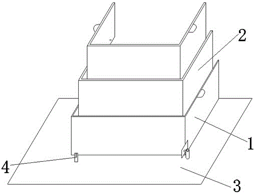
[0017] refer to figure 1 A lifting water retaining cover as shown includes an outer cover plate 1 and a two-layer inner cover plate 2. Both the outer cover plate 1 and the inner cover plate 2 are concave structures composed of three panels; Installed on the worktable 3 of the wire EDM machine.

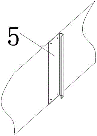
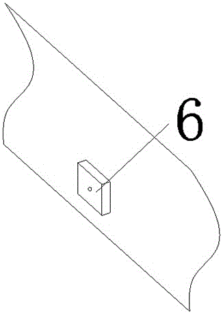
[0018] refer to figure 2 and image 3 As shown, the inner sides of the two opposite panels of the outer cover plate 1 are respectively provided with a unilateral iron groove 5 along the vertical direction, and the outer sides of the two opposite panels of the inner cover plate 2 are correspondingly equipped with a matching unilateral iron groove 5. Magnet 6, the inner side of the two opposite panels of the inner cover plate 2 are also respectively provided with a unilateral iron slot 5 along the vertical direction, and the unilateral iron slot 5 and the magnet 6 on both sides of the same inner cover plate 2 do not overlap each other. , so as not to affect the adsorption between two...


PUM


Abstract

The invention relates to a lifted and pulled water-retaining cover.The lifted and pulled water-retaining cover comprises an outer cover plate and one or more layers of inner cover plates, the outer cover plate and the inner cover plates are each of a concave structure composed of three panels, the inner sides of the two opposite panels of the outer cover plate are each provided with a single-side iron groove in the vertical direction, the outer sides of the two opposite panels of each inner cover plate are each provided with a magnet matched with the corresponding single-side iron groove, and the inner sides of the two opposite panels of each inner cover plate are each provided with a single-side iron groove in the vertical direction; every two adjacent cover plates are connected with each other through the corresponding magnet and the single-side iron groove.The lifted and pulled water-retaining cover is simple in structure and reliable to mount, the problems that a workbench water retaining cover on a traditional electrical discharge linear cutting machine is difficult to mount, and workpieces are difficult to mount are solved, and meanwhile the peripheral construction environment can be better protected.

Description

technical field [0001] The invention relates to a wire electric discharge machine tool, in particular to a lifting water retaining cover used on a working table of a wire electric discharge machine tool. Background technique [0002] Wire-cut electric discharge machine is mainly used for the manufacture of various molds, electrodes, precision parts, complex cavities of various conductors such as hard alloy, hardened steel, graphite, aluminum alloy, structural steel, stainless steel, titanium alloy, diamond, etc. and surface machining. Using computer control system, all Chinese automatic drawing programming, control software. There are trajectory and time display during processing, and you can know the processing situation at any time. The wire walking has the feature of multiple cutting functions. [0003] In order to prevent the pollution of the operating environment by the mist and splash of the emulsion in the existing wire electric discharge machine tool, the workbench...

Claims


Application Information

Patent Timeline
IPC IPC(8): B23H11/00
CPCB23H11/00
Inventor 杨荆浩
Owner 上海略云精密数控机床有限公司
Why Eureka
Try Eureka