A gantry type grinding device

A grinding device, gantry-type technology, applied in the direction of grinding drive device, grinding machine, grinding workpiece support, etc., can solve the problems of poor grinding stability, tool precision and flatness, etc., to improve grinding precision, improve precision, ensure omnidirectional effect

Active Publication Date: 2018-01-02
马鞍山市金德瑞冶金机械配件制造有限公司
View PDF10 Cites 0 Cited by
  • Summary
  • Abstract
  • Description
  • Claims
  • Application Information

AI Technical Summary

Problems solved by technology

[0007] In view of the poor grinding stability of the high-speed steel tool grinding device in the prior art, which leads to poor tool precision and flatness, the present invention provides a gantry-type grinding device

Method used


Image

  • A gantry type grinding device
  • A gantry type grinding device
  • A gantry type grinding device

Examples


Embodiment 1

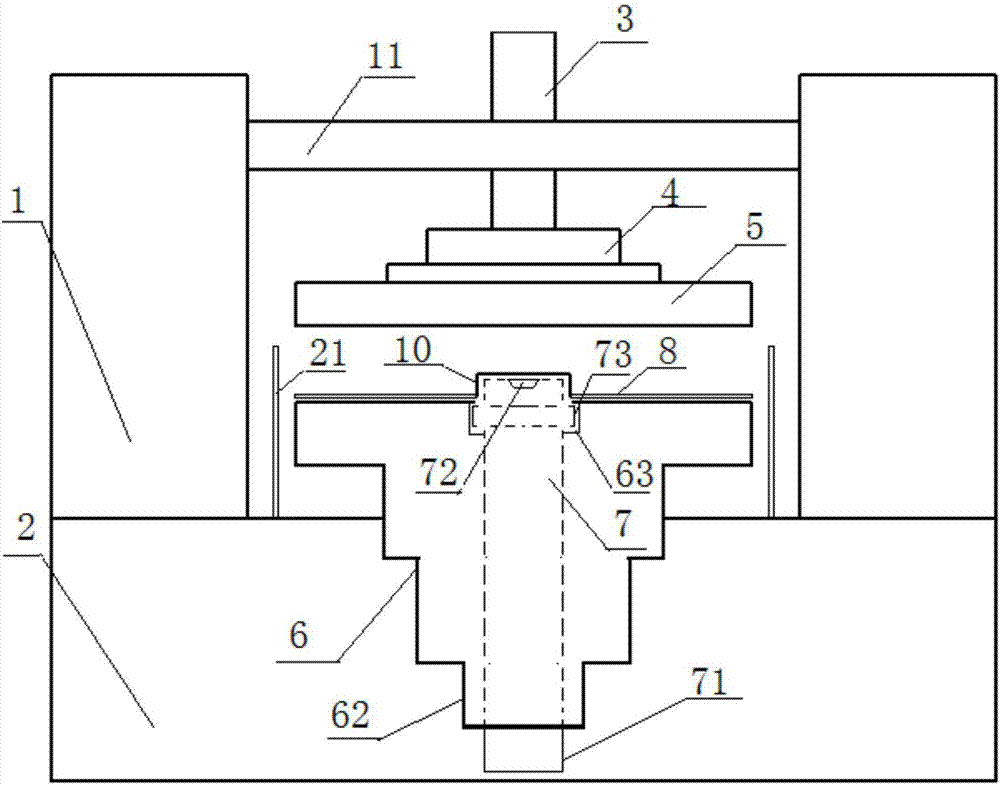
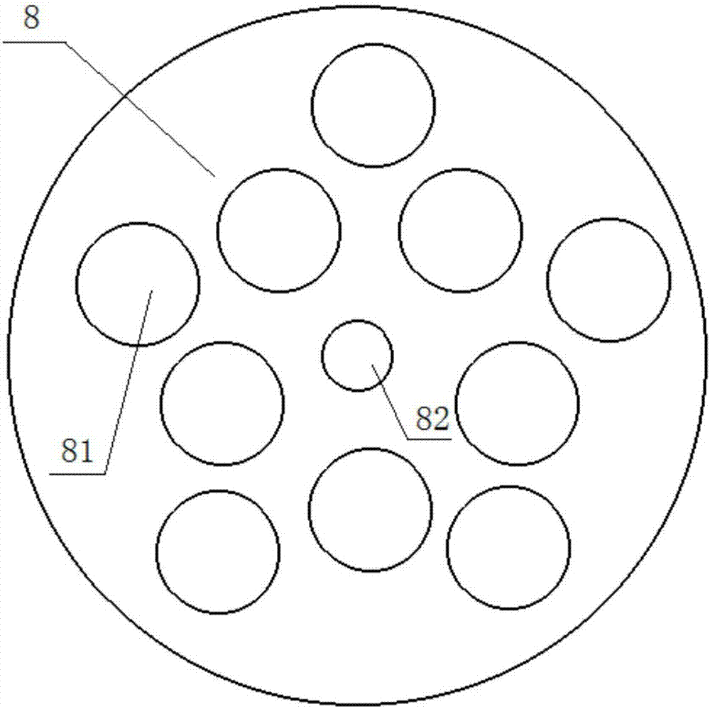
[0040] A kind of gantry grinding device of the present embodiment, such as figure 1 As shown, it includes an upper grinding disc 5 and a lower grinding disc 6 that are set up and down on the grinding surface, and also includes a gantry frame 1, a central shaft 7 and a mold 8, wherein: the upper grinding disc 5 is placed under the gantry beam 11 of the gantry frame 1 through a hydraulic rod 3 Reciprocate vertically up and down; the middle part of the lower millstone 6 has a vertical cavity through which the central axis 7 is inserted; Such as figure 2 As shown, the mold 8 is evenly distributed with 10 tool locking holes 81 with a diameter of 300mm. The lower grinding disc 6 and the central shaft 7 are all driven by the pulley to rotate, and the two are the same driving wheel, but the diameter of the driven wheel is different; the thickness of the mold 8 is less than the thickness of the tool to be processed.

[0041] The method that the gantry type grinding device of the pre...

Embodiment 2

[0050] Similar to Embodiment 1, the improvement is that: the pillars on both sides of the gantry 1 are vertically fixed on the upper surface of the platform 2; the compression rod of the hydraulic rod 3 passes through the gantry beam 11 and is fixedly connected to the upper grinding table 5; the central shaft 7 drives the mold 8 Eccentric rotation. The rotating speed of lower millstone 6 is greater than the rotating speed of mold 8. A grinding liquid cavity is arranged inside the upper grinding disc 5, and grinding liquid spraying holes are uniformly arranged on the lower surface, so that the grinding liquid can be sprayed continuously and more evenly. The rotational speed of the central shaft 7 is 20% of the rotational speed of the lower grinding disc 6 .

[0051] The method that the gantry type grinding device of the present embodiment produces the high-speed steel cutting tool, its steps are:

[0052] A. Fill 10 pieces of cutting tools with a diameter of 200 mm into the c...

Embodiment 3

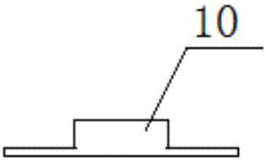
[0059] Similar to Embodiment 2, the improvement is: it also includes 2 stabilizing sleeves 4 and eccentric pin 9, protective cover 10, and is arranged on the periphery of the lower grinding disc 6, the grinding liquid pool 21 on the upper surface of the platform 2; the stabilizing sleeve 4 is Concentric with the upper grinding disc 5, fixed on the upper surface of the upper grinding disc 5, the compression rod of the hydraulic rod 3 passes through the stabilizing sleeve 4. After the two stabilizing sleeves 4 are fixedly connected, they are stacked on the upper grinding disc 5 in a stepped shape with a small upper part and a larger lower part. surface. The upper part of the cavity of the lower grinding disc 6 is a stepped hole 63, and the upper part of the central shaft 7 is provided with an annular protrusion 73. The diameter of the annular protrusion 73 is slightly smaller than the diameter of the stepped hole 63, and is embedded in the stepped hole 63 to stabilize the rotatio...


PUM

PropertyMeasurementUnit
surface smoothnessaaaaaaaaaa

Abstract

The invention discloses a gantry grinding device and belongs to the technical field of blade grinding.The gantry grinding device comprises an upper grinding disc and a lower grinding disc, wherein the grinding face of the upper grinding disc and the grinding face of the lower grinding disc are in vertically opposite fit, and the device further comprises a portal frame, a center shaft and a die; the upper grinding disc conducts vertical and reciprocating motion up and down below a gantry beam of the portal frame through a hydraulic rod; a vertical cavity penetrates through the middle of the lower grinding disc, and the center shaft is inserted into the cavity; the die is consistent with the upper grinding disc and the lower grinding disc in shape, and the middle of the die is fixedly connected with the top end of the center shaft.According to the gantry grinding device, the center shaft and the die are fixedly connected to drive the die and the lower grinding disc to move in the same direction, the die has a function of positioning a cutter, the situation that cutter precision, planeness and product consistency are affected due to displacement of the cutter is avoided, and dual possibility for further improving grinding precision of a high-speed steel cutter is provided through the cooperative function among the portal frame, the center shaft and the die.

Description

technical field [0001] The invention belongs to the technical field of blade grinding, and in particular relates to a gantry type grinding device. Background technique [0002] With the rapid development and progress of society, the scope of use of knives is gradually expanding, ranging from the manufacture of light industries such as daily necessities to heavy industries such as construction and military. Development is also increasing rapidly. [0003] In recent years, the knives and scissors hardware industry has developed greatly, and the export trade volume is increasing year by year. According to statistics, there are about 3,000 enterprises engaged in the production of knives and scissors in my country, and the annual gross industrial output value of knives and scissors is about 10 billion yuan. , The annual foreign exchange earning from export exceeds 400 million US dollars. Daily hardware products such as kitchen knives, knife sets, pocket knives, ceramic knives, i...

Claims


Application Information

Patent Timeline
Patent Type & Authority Patents(China)
IPC IPC(8): B24B3/36B24B41/06B24B47/06B24B47/12
CPCB24B3/36B24B27/0076B24B27/0092B24B41/06B24B47/06B24B47/12
Inventor 尹秀江
Owner 马鞍山市金德瑞冶金机械配件制造有限公司
Why Eureka
Try Eureka