Supercharge Your Innovation With Domain-Expert AI Agents!

Mounting device for knife tool of cutting machine

An installation device and cutting machine technology, applied in the direction of metal processing, etc., can solve the problems of difficult disassembly, low stability, no tool side edge protection device, etc., and achieve the effect of not easy disassembly

Inactive Publication Date: 2016-07-13
TIANJIN RUIFENG ELECTROPLATING PROCESSING CO LTD
View PDF0 Cites 0 Cited by
  • Summary
  • Abstract
  • Description
  • Claims
  • Application Information

AI Technical Summary

Problems solved by technology

[0003] The problem to be solved by the invention is that the general tool installation only connects the tool, and there is no protection device for the side edge of the tool, and the tool is installed and controlled in a fixed connection, which is not easy to disassemble and has low stability

Method used


Image

  • Mounting device for knife tool of cutting machine

Examples


Embodiment Construction

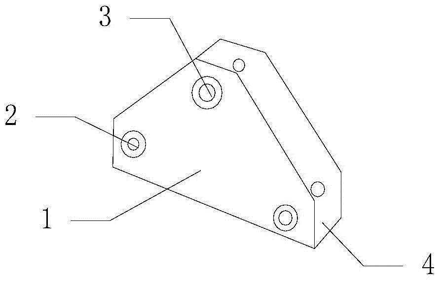
[0013] Such as figure 1 As shown, the installation device for cutting tools includes a U-shaped groove, mounting holes 2 on both sides of the U-shaped groove 4, and elastic clips arranged in the U-shaped groove 4. The U-shaped groove 4 includes a groove The wall 1 and the connecting hole 3 provided at the end of the groove wall 1 for installing a tool.

[0014] The U-shaped groove 4 is provided with mounting holes 2 on both horizontal sides of the U-shaped groove 4, the U-shaped groove 4 is provided with elastic clamps, and the U-shaped groove 4 has an extended groove wall 1 on the side wall. The shape of the groove wall 1 is trapezoidal, and the end of the groove wall 1 is provided with a connecting hole 3.

[0015] Further, the inner wall of the elastic clip close to the tool is provided with a non-slip pad, the material of the elastic clip is phosphor bronze, beryllium bronze, manganese steel or stainless steel, and the number of the elastic clip can be 2 to 4 .

[0016] Furthe...


PUM


Abstract

The invention provides a mounting device for a knife tool of a cutting machine. The mounting device for the knife tool of the cutting machine comprises a U-shaped groove, mounting holes and elastic clamping clips, wherein the mounting holes are located in the two sides of the U-shaped groove; the elastic clamping clips are arranged in the U-shaped groove; the U-shaped groove comprises groove walls and connecting holes which are formed in the tail ends of the groove walls and are used for mounting the knife tool; the two horizontal sides of the U-shaped groove are provided with the mounting holes of the U-shaped groove; the elastic clamping clips are arranged inside the U-shaped groove; side walls of the U-shaped groove are provided with the extending groove walls; the shapes of the groove walls are trapezoidal; the tail ends of the groove walls are provided with the connecting holes. In a general knife tool mounting process, a knife tool is only connected, a protecting device for the side edge of the knife tool does not exist, moreover, the mounting and control way of the knife tool is fixed connection, the disassembly is difficult, and the stability is low; according to the mounting device for the knife tool of the cutting machine, the stability at a joint of the knife tool is effectively controlled by the elastic clamping clips in the U-shaped groove, and the side surfaces of the knife tool are effectively protected by the side walls.

Description

Technical field [0001] The invention relates to a mounting device for cutting tools. Background technique [0002] The general tool installation only connects the tool, and there is no protection device for the side edge of the tool, and the tool is installed and controlled in a fixed connection, which is not easy to disassemble and has low stability. Summary of the invention [0003] The problem to be solved by the invention is that the general tool installation only connects the tool, and there is no protection device for the side edge of the tool, and the tool is installed and controlled in a fixed connection, which is not easy to disassemble and has low stability. [0004] In order to solve the above-mentioned technical problems, the present invention adopts a technical solution: an installation device for cutting tools includes a U-shaped groove, installation holes on both sides of the U-shaped groove, and elastic clamps arranged in the U-shaped groove. The U-shaped groove inc...

Claims


Application Information

Patent Timeline
Patent Type & Authority Applications(China)
IPC IPC(8): B26D7/26
Inventor 朱宝权
Owner TIANJIN RUIFENG ELECTROPLATING PROCESSING CO LTD
Features
  • R&D
  • Intellectual Property
  • Life Sciences
  • Materials
  • Tech Scout
  • Unparalleled Data Quality
  • Higher Quality Content
  • 60% Fewer Hallucinations
Learn More