Machinery punching assembly

A technology for mechanical punching and assembly, applied in metal processing and other directions, can solve the problems of low safety, unsuitable for a large number of binding occasions, and low practicability, and achieve the effect of improving work efficiency, improving quality, and strong practicability.

Inactive Publication Date: 2016-07-13
CHONGQING HECHUAN HUANYU FITTINGS FACTORY
View PDF0 Cites 0 Cited by
  • Summary
  • Abstract
  • Description
  • Claims
  • Application Information

AI Technical Summary

Problems solved by technology

At present, paper binding holes are mainly made manually. Workers place the stacked papers flat and then punch holes with drills, which is time-consuming, laborious, inefficient, and the quality of punching is not high, so it is not suitable for occasions that require a large number of bindings; or At present, although there are automatic punching machines, their structure is complex, the operation is cumbersome, the practicability is not strong, and the safety is low.

Method used


Image

  • Machinery punching assembly

Examples


Embodiment Construction

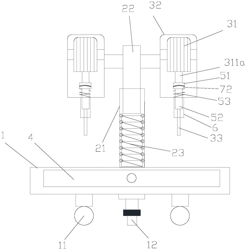
[0012] like figure 1 Shown: In this preferred embodiment, the mechanical punching assembly includes a machine base 1, a lifting mechanism and a punching mechanism, and the lifting mechanism includes a hollow outer rod 21 vertically arranged on the machine base 1, a coaxial The inner rod 22 sleeved in the outer rod 21 and the elastic return member 23 arranged in the outer rod 21 and abutting against the bottom of the inner rod 22; the roller 11 is provided under the base 1; the punching mechanism includes a motor 31. Machine box 32 and drill 33 for punching, the motor 31 is fixed in the machine box 32, the machine box 32 is fixedly connected with the inner rod 22, the crankshaft of the motor 31 faces downward and the crankshaft Pass through machine box 32 and drill bit 33 transmission connection; Described machine shaft comprises upper shaft 311a and the lower shaft 311b that is connected with described upper shaft 311a by slipping mechanism, when the transmission between descr...


PUM


Abstract

The invention discloses a binding puncher comprising a pedestal, an elevating mechanism and a punching mechanism; the elevating mechanism comprises a hollow outer rod vertically arranged on the pedestal, an inner rod coaxially sleeved in the outer rod, and an elastic recovery piece arranged in the outer rod and abutting against the bottom of the inner rod; rollers are arranged under the pedestal; the punching mechanism comprises motors, machine boxes, and drill tools used for punching; the motor is fixed in the machine box; the machine box is fixedly connected with the inner rod; a motor shaft of the motor faces downwards, penetrates the machine box, and is in transmission connection with the drill tool; the motor shaft comprises an upper shaft and a lower shaft connected with the upper shaft through a skid mechanism; when the transmission moment between the upper and lower shafts exceeds the preset moment, the skid mechanism disconnects; the drill tool is a hollow structure; through holes matched with the drill tools are arranged on the corresponding portions of the pedestal; the pedestal is also provided with a detachable push-and-pull box connected with the through holes; the machinery punching assembly can improve work efficiency.

Description

technical field [0001] The invention relates to an office equipment, in particular to a mechanical punching assembly. Background technique [0002] The preservation and filing of paper documents requires binding, which is generally completed by a binding machine. During the binding process of the binding machine, it is necessary to use a puncher to punch holes in the paper, and then complete the pressure riveting or lead binding. At present, paper binding holes are mainly made manually. Workers place the stacked paper flat and then punch holes with a drill, which is time-consuming, laborious, inefficient, and the quality of punching is not high, so it is not suitable for occasions that require a large number of bindings; or At present, although there is also an automatic punching machine, its structure is complex, its operation is cumbersome, its practicability is not strong, and its safety is low. Contents of the invention [0003] In order to solve the above technical ...

Claims


Application Information

Patent Timeline
Patent Type & Authority Applications(China)
IPC IPC(8): B26F1/16
Inventor 刘林鑫
Owner CHONGQING HECHUAN HUANYU FITTINGS FACTORY
Why Eureka
Try Eureka