3D model lifting cylinder for 3D printer

A technology of 3D printers and lifting cylinders, which is applied to the sealing of engines, electromechanical devices, mechanical equipment, etc., can solve problems that affect printing quality, sealing performance cannot meet the requirements, gas waste, etc., and achieve the requirements of sealing and quality assurance Effect

Inactive Publication Date: 2016-07-13
FOSHAN NANHAI ZHONGNAN MACHINERY
View PDF0 Cites 2 Cited by
  • Summary
  • Abstract
  • Description
  • Claims
  • Application Information

AI Technical Summary

Problems solved by technology

[0004] The purpose of the present invention is to provide a 3D model lifting cylinder for a 3D printer, which aims to solve the problem that the sealing of the existing lifting

Method used


Image

  • 3D model lifting cylinder for 3D printer
  • 3D model lifting cylinder for 3D printer

Examples


Example Embodiment

[0012] In order to make the objectives, technical solutions and advantages of the present invention clearer and clearer, the present invention will be further described in detail below with reference to the drawings and embodiments.

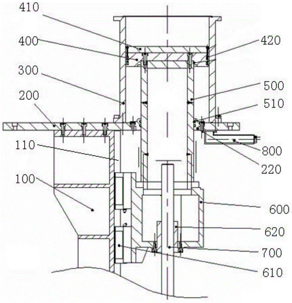
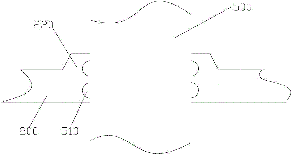
[0013] Such as figure 1 with figure 2 As shown, the 3D model lifting cylinder of the 3D printer includes a bracket 100, a bottom plate 200, a cylinder block 300, a piston 400, a guide rod 500, a nut seat 600, and a screw rod 700. The bottom plate 200 is fixed on the bracket 100 and the cylinder block 300 Fixed on the bottom plate 200, the bottom plate 200 is provided with a guide rod through hole; the bracket 100 is provided with a slide rail 110, and the nut seat 600 is provided with a sliding block 610. The sliding block 610 is clamped to slide on the slide rail 110, so The screw rod 700 is connected to the nut seat 600 through the screw nut 620, and the screw rod 700 is externally connected to the servo motor; the upper end of the guide rod 500 ...


PUM


Abstract

The invention discloses a 3D lifting cylinder for a 3D printer. According to the 3D model lifting cylinder, two sealing structures are simultaneously arranged between a piston and a cylinder body and between a guide rod and a baseplate insert; even one of the sealing structures has a poor sealing effect, the other sealing structure can also ensure the sealability of the whole lifting cylinder body to play a double sealing effect, thus ensuring the sealing requirement of a forming chamber and ensuring the printing quality; meanwhile, a collecting box is arranged in a position where the cylinder body is connected with the baseplate insert, and is used for collecting metal powder, such that the loss of the movement precision when the metal powder floats into a sliding block of a sliding rail, or screw rod is avoided.

Description

Technical field [0001] The invention relates to the field of 3D printing equipment, in particular to a 3D model lifting cylinder of a 3D printer. Background technique [0002] The model lifting cylinder of the 3D printer drives the screw rod to rotate through the servo motor, and uses the guide of the slide rail to realize the up and down movement of the piston, thereby driving the up and down expansion and contraction of the 3D model being printed during the printing process. The molding room of the 3D printer requires absolute sealing. During the movement of the lifting cylinder, inert gas in the molding room may enter the lifting cylinder. The existing lifting cylinder does not meet the requirements for sealing, resulting in inert gas in the molding room. The elevating cylinder body flows out of the outdoor, causing waste of gas, and also causing outdoor gas to flow into the molding room, causing indoor gas pollution and affecting the quality of printing. [0003] Therefore, th...

Claims


Application Information

Patent Timeline
IPC IPC(8): F16H25/20F16H25/24F16H57/029F16J15/16H02K7/10B08B15/04
Inventor 林堂伟罗有旺杨炽洪梁翱
Owner FOSHAN NANHAI ZHONGNAN MACHINERY
Why Eureka
Try Eureka