Supercharge Your Innovation With Domain-Expert AI Agents!

Heat dissipation device for electromechanical equipment

A heat dissipation device, electromechanical equipment technology, applied in the direction of electrical digital data processing, cooling/ventilation/heating transformation, instrument, etc., can solve the problem of high price of semiconductor refrigeration and heat dissipation devices, low heat dissipation efficiency of air-cooled heat dissipation devices, thick heat dissipation devices, etc. Problems, to achieve the effect of small space occupation, faster fluidity, and avoid damage due to corrosion

Inactive Publication Date: 2016-07-13
泰州市海陵区固泰标准件厂
View PDF0 Cites 1 Cited by
  • Summary
  • Abstract
  • Description
  • Claims
  • Application Information

AI Technical Summary

Problems solved by technology

[0002] Electromechanical equipment such as distribution boxes, control boxes, switch cabinets, and computer boxes will generate a lot of heat when the equipment is running. In order to ensure the normal operation of the electromechanical equipment, it is ensured that the distribution boxes, control boxes and other equipment will not be damaged due to high temperature. , usually it is necessary to install a cooling device on the box body. There are two types of existing cooling devices: semiconductor cooling and air cooling. The semiconductor cooling device is relatively expensive and does not have universality. , the heat sink is too thick and takes up too much space

Method used


Image

  • Heat dissipation device for electromechanical equipment
  • Heat dissipation device for electromechanical equipment

Examples


Embodiment Construction

[0014] The following will clearly and completely describe the technical solutions in the embodiments of the present invention with reference to the accompanying drawings in the embodiments of the present invention. Obviously, the described embodiments are only some, not all, embodiments of the present invention. Based on the embodiments of the present invention, all other embodiments obtained by persons of ordinary skill in the art without making creative efforts belong to the protection scope of the present invention.

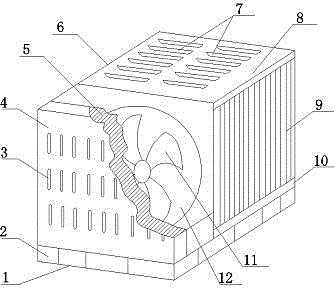
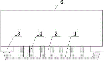
[0015] see Figure 1~2 , in an embodiment of the present invention, a cooling device for electromechanical equipment, including a mounting base 1, a box body 6, a cooling chamber 8 and a fan 11, the bottom of the box body 6 is screwed to the mounting base 1 through mounting feet 13, and the box body 6 is connected to the Several support plates 14 are arranged between the installation bases 1, and some support plates 14 are arranged in parallel, and some air pa...


PUM


Abstract

The invention discloses a heat dissipation device for electromechanical equipment. The heat dissipation device comprises a mounting base, a box, a heat dissipation bin and a fan, wherein the bottom of the box is in threaded connection with the mounting base through mounting feet, a plurality of support plates are arranged between the box and the mounting base, a plurality of air holes are formed among the support plates, a front baffle is arranged at the front end of the box, a plurality of kidney-shaped holes are formed in the front baffle, a filter layer is arranged at the back end of the front baffle, an air suction hole is formed behind the filter layer, a fan is mounted in the air suction hole, the back end of the air suction hole is connected with the heat dissipation bin, a plurality of air outlets are formed in the upper surface of the heat dissipation bin, and heat dissipation strips are arranged on two sides and at the bottom of the heat dissipation bin. The whole heat dissipation device is mounted in the box, cannot be damaged due to collisions, occupies small space and is convenient to move, easy to mount and applicable to heat dissipation of electromechanical equipment such as distribution boxes, control boxes, switch cabinets and computer cases during equipment operation.

Description

technical field [0001] The invention relates to the technical field of electromechanical equipment, in particular to a cooling device for electromechanical equipment. Background technique [0002] Electromechanical equipment such as distribution boxes, control boxes, switch cabinets, and computer boxes will generate a lot of heat when the equipment is running. In order to ensure the normal operation of the electromechanical equipment, it is ensured that the equipment such as distribution boxes and control boxes will not be damaged due to high temperature. , usually it is necessary to install a cooling device on the box body. There are two types of existing cooling devices: semiconductor refrigeration and air cooling. , the heat sink is too thick and takes up too much space. Contents of the invention [0003] The object of the present invention is to provide a heat dissipation device for electromechanical equipment to solve the problems raised in the background art above. ...

Claims


Application Information

Patent Timeline
Patent Type & Authority Applications(China)
IPC IPC(8): G06F1/20H05K7/20
Inventor 顾同春
Owner 泰州市海陵区固泰标准件厂
Features
  • R&D
  • Intellectual Property
  • Life Sciences
  • Materials
  • Tech Scout
  • Unparalleled Data Quality
  • Higher Quality Content
  • 60% Fewer Hallucinations
Learn More