
Semiconductor device and manufacturing method thereof

A manufacturing method and semiconductor technology, applied in the direction of semiconductor devices, semiconductor/solid-state device manufacturing, electrical components, etc., can solve the problems of no solution, high electric field strength, large conductive channel stress, etc.

Inactive Publication Date: 2016-07-13
SEMICON MFG INT (SHANGHAI) CORP
View PDF4 Cites 1 Cited by
  • Summary
  • Abstract
  • Description
  • Claims
  • Application Information

AI Technical Summary

Problems solved by technology

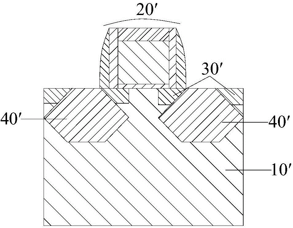
[0004] In the above-mentioned semiconductor device, since the stress layer 40' under the gate structure 20' has a pointed structure, the electric field strength near it is relatively high, thus easily generating junction leakage current between the stress layer 40' and the substrate 10'
At the same time, the lightly doped region 30' close to the conductive channel is replaced by a part of the stress layer 40', so that the stress under the conductive channel is greater, which in turn makes the junction leakage current more likely to occur
For the above problems, there is currently no effective solution

Method used


Image

  • Semiconductor device and manufacturing method thereof
  • Semiconductor device and manufacturing method thereof
  • Semiconductor device and manufacturing method thereof

Examples


Embodiment Construction

[0031] It should be noted that, in the case of no conflict, the embodiments in the present application and the features in the embodiments can be combined with each other. The present application will be described in detail below with reference to the accompanying drawings and embodiments.

[0032] It should be noted that the terminology used here is only for describing specific implementations, and is not intended to limit the exemplary implementations according to the present application. As used herein, unless the context clearly indicates otherwise, the singular form is also intended to include the plural form. In addition, it should also be understood that when the terms "comprising" and / or "comprising" are used in this specification, it indicates There are features, steps, operations, means, components and / or combinations thereof.

[0033] For the convenience of description, spatially relative terms may be used here, such as "on ...", "over ...", "on the surface of ..."...


PUM


Abstract

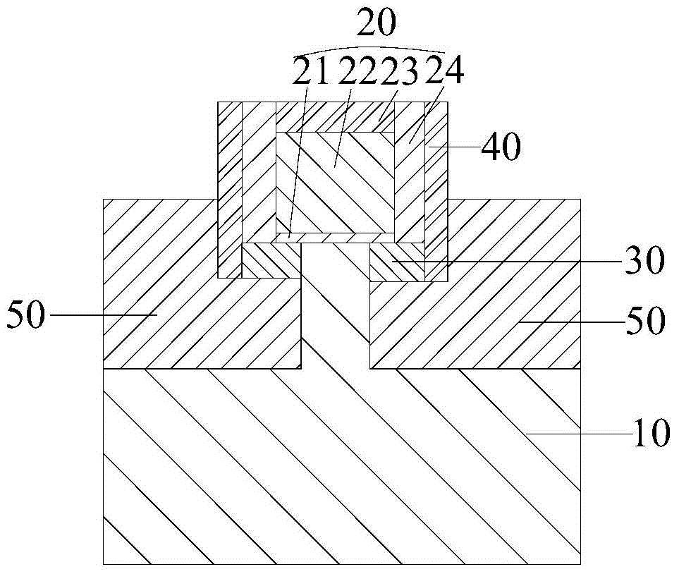
The invention discloses a semiconductor device and a manufacturing method thereof. The semiconductor device comprises a substrate; a gate structure disposed on the surface of the substrate; a lightly doped region arranged in the substrate on the two sides of the gate structure and extending to be below the gate structure; an L-shaped groove and a stress layer in the L-shaped groove. The L-shaped groove is arranged in the substrate on the two sides of the gate structure. One part of the stress layer is arranged below the lightly doped region. The stress layer below the lightly doped region is of a cuboid structure. In this way, the formation of a tip structure between the stress layer and the substrate is avoided, so that the junction leakage current caused by the tip structure is avoided. Meanwhile, below a conductive channel, the stress layer of the cuboid structure is away from the conductive channel compared with a sigma-type stress layer. Therefore, the stress below the conductive channel is reduced, and the junction leakage current is further reduced.

Description

technical field [0001] The present application relates to the technical field of semiconductor integrated circuits, and in particular, to a semiconductor device and a manufacturing method thereof. Background technique [0002] As the integration of transistors in semiconductor devices becomes higher and higher, the feature size of transistors becomes smaller and smaller, and the mobility of carriers in transistors gradually decreases. This decrease in carrier mobility will not only reduce the switching speed of the transistor, but also reduce the driving current of the transistor, which ultimately leads to a decrease in the device performance of the transistor. In the prior art, technicians use stress technology, that is, by introducing local unidirectional tensile or compressive stress to the conduction channel of the transistor, so as to increase the mobility of carriers in the conduction channel of the transistor. For example, a SiGe layer is usually embedded in a PMOS d...

Claims


Application Information

Patent Timeline
Patent Type & Authority Applications(China)
IPC IPC(8): H01L29/78H01L29/06H01L21/336
Inventor 赵猛
Owner SEMICON MFG INT (SHANGHAI) CORP
Learn More