Simple cable fixing rack

A fixing frame and cable technology, applied in the direction of electrical components, etc., can solve the problems of increased cost, easy corrosion of angle iron brackets, and many processes, and achieve the effects of prolonging service life, stable welding method, and flexible and easy installation

Inactive Publication Date: 2016-07-13
XIAN MEIYU INFORMATION TECH
View PDF0 Cites 4 Cited by
  • Summary
  • Abstract
  • Description
  • Claims
  • Application Information

AI Technical Summary

Problems solved by technology

The production process of traditional angle iron brackets consumes a lot of energy, many processes, and a long cycle, and the product quality cannot be guaranteed
In many harsh environmental conditions, such as subways, tunnels, chemical enterprises, rainy and humid or coastal salt spray, etc., the use of angle iron brackets is easy to rust, the maintenance cost of the facilities is high, and the service life is short
In terms of a

Method used


Image

  • Simple cable fixing rack

Examples


Example Embodiment

[0018] Example 1

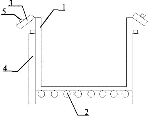
[0019] A simple cable fixing frame is composed of transverse ribs 1 and longitudinal ribs 2. The cross-section of the fixing frame is a U-shaped groove structure, and the longitudinal ribs 2 are fixedly arranged outside the transverse ribs 1.

Example Embodiment

[0020] Example 2

[0021] Example 2 such as figure 1 As shown, it is improved on the basis of embodiment 1. Its transverse rib 1 and longitudinal rib 2 are metal pipes, transverse rib 1 is U-shaped structure, longitudinal rib 2 is linear structure, transverse rib 1 and longitudinal rib 2 are fixed by welding . Compared with the existing fixing frame, the material cost is reduced, and the degree of integration is more complete. The grid structure makes the installation easier and easier and faster when the line is overhauled.

Example Embodiment

[0022] Example 3

[0023] Example 3 such as figure 1 As shown, it is an improvement on the basis of embodiment 1. There is a movable cable clamp 3 on each side of the transverse rib 1. When the cable is connected, there will be shaking. When the cable is shaken, the edge of the cable holder will be worn out, causing the cable to be worn and scrapped. The movable cable clamp can reach the splint. The cable holder and the cable will follow the movement, and no relative displacement will occur. Wear.


PUM


Abstract

The invention discloses a simple cable fixing rack, and belongs to the technical field of cable accessories. The rack consists of a lateral rib 1 and a longitudinal rib 2. The cross section of the rack is in a U-shaped groove structure, and the longitudinal rib 2 is fixedly disposed at an outer side of the lateral rib 1. The lateral rib 1 and the longitudinal rib 2 are metal pipes, wherein the lateral rib 1 is in a U-shaped structure and the longitudinal rib 2 is in a linear structure. The lateral rib 1 and the longitudinal rib 2 are fixed through welding. Two sides of the lateral rib 1 are respectively provided with a movable cable clamping plate 3, and the movable cable clamping plates 3 are provided with an annular cable fixing device 5. Two sides of the lateral rib 1 are respectively provided with an adjustable vertical support 4. The rack is simple in structure, is simple and convenient in installation, shortens the installation time, can reduce the manufacture cost, saves the raw materials, is good in heat dissipation performance, and prolongs the service life of a cable.

Description

technical field [0001] The invention relates to the technical field of electrical equipment, in particular to a simple cable fixing frame for fixing cables, in particular to a simple cable fixing frame. Background technique [0002] When laying wires and cables, it is necessary to use a fixing bracket to fix the cable. The existing fixing bracket is a steel plate that is bent into a groove shape, then the cable is placed in the groove, and a cover is added on it. The bracket is usually a corner The iron profiles are assembled by welding or fasteners. The production process of traditional angle iron brackets consumes a lot of energy, has many procedures, and a long cycle, and the product quality cannot be guaranteed. In many harsh environmental conditions, such as subways, tunnels, chemical companies, rainy and humid or coastal salt spray, etc., the use of angle iron brackets is easy to rust, the maintenance cost of the facilities is high, and the service life is short. In ...

Claims


Application Information

Patent Timeline
IPC IPC(8): H02G3/04
Inventor 巨杰
Owner XIAN MEIYU INFORMATION TECH
Why Eureka
Try Eureka