Full wave inductance current sampling circuit

A technology of inductive current and sampling circuit, applied in the direction of measuring current/voltage, electrical components, adjusting electrical variables, etc., can solve problems such as circuit mismatch, system instability, system false triggering, etc., and achieve the goal of avoiding glitches and continuous sampling signals Effect

Active Publication Date: 2016-07-13
拓尔微电子股份有限公司
View PDF5 Cites 21 Cited by
  • Summary
  • Abstract
  • Description
  • Claims
  • Application Information

AI Technical Summary

Problems solved by technology

Although this method obtains full-wave inductor current information, there are still many shortcomings.
First, due to the power switch M ip conduction and power switch M in There is a dead time between turn-on and switch S 1 ~S 4 action, resulting in many glitches in the detected current waveform during switching, such as Figure 4 As shown, this can cause the system to falsely trigger
Second, due to the problem of circuit mismatch, the detected current waveform will change abruptly when switching (such as Figure 4 As shown within the dotted ellipse, the sampling voltage V sen sudden change), but in fact the inductor current is impossible to have a sudden change, which may cause system instability

Method used


Image

  • Full wave inductance current sampling circuit
  • Full wave inductance current sampling circuit
  • Full wave inductance current sampling circuit

Examples


Embodiment Construction

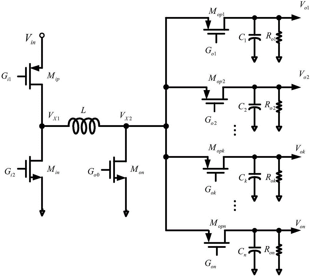
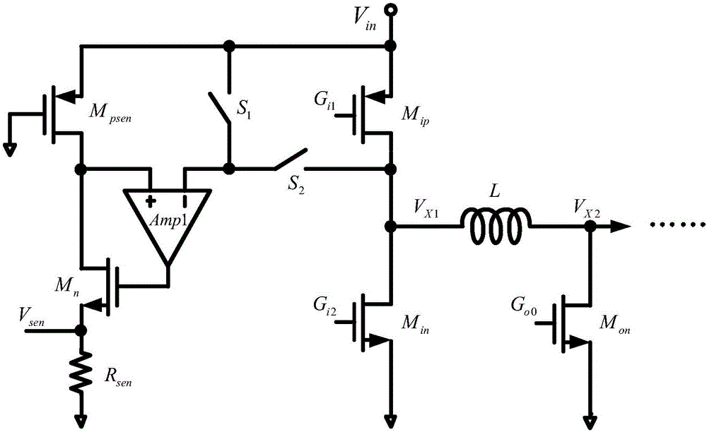
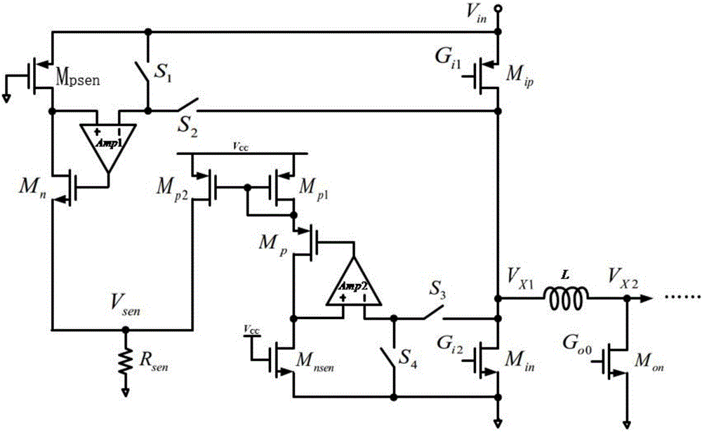
[0024] refer to Figure 5 , a full-wave inductor current sampling circuit of the present invention includes a system power stage circuit, a proportional MOS tube current sampling circuit, a voltage-to-current and current summation circuit, and a sampling DC correction and sampling integration circuit, the first of the system power stage circuit One output terminal is further connected to the first input terminal of the sampling DC correction and sampling integration circuit through the proportional MOS tube current sampling circuit, and the second output terminal of the system power stage circuit is further connected to the sampling circuit through the voltage-to-current and current summation circuit The second input end of the DC correction and sampling integration circuit.

[0025] As a further preferred embodiment, the system power stage circuit includes a first PMOS transistor M1, a first NMOS transistor N1, a second NMOS transistor N2 and an inductor L, and the source of ...


PUM


Abstract

The invention discloses a full wave inductance current sampling circuit, comprising a system power level circuit, a proportion MOS tube current sampling circuit, a voltage-current and current summation circuit, and a sampling direct current correction and sampling integration circuit. The first output terminal of the system power level circuit is connected to the first input terminal of the sampling direct current correction and sampling integration circuit through the proportion MOS tube current sampling circuit, and the second output terminal of the system power level circuit is in connection with the second input terminal of the sampling direct current correction and sampling integration circuit through the voltage-current and current summation circuit. The full wave inductance current sampling circuit can realize accurate full wave inductance current sampling through the system power level circuit, the proportion MOS tube current sampling circuit, the voltage-current and current summation circuit, and the sampling direct current correction and sampling integration circuit, obtain continuous sampling signals, effectively avoid burrs, and be widely applied to the electronic circuit field.

Description

technical field [0001] The invention relates to the technical field of electronic circuits, in particular to a full-wave inductor current sampling circuit. Background technique [0002] Single-inductor multiple-output (Single-Inductor Multiple-Output, SIMO) DC-DC converter is a new type of DC-DC converter structure that multiplexes inductors in time. The system only needs one inductor to provide multiple independent outputs. . Therefore, the number of off-chip inductors is greatly reduced, the volume of the converter is reduced, and the cost is reduced. In recent years, the automatic buck-boost single-inductance multi-output DC-DC converter has expanded the application range of this type of converter. [0003] The power stage circuit of the automatic lifting type single-inductance multi-output DC-DC converter is as follows: figure 1 As shown, the power stage circuit includes an input stage switch group and an output stage switch group, wherein the input stage switch group...

Claims


Application Information

Patent Timeline
Patent Type & Authority Applications(China)
IPC IPC(8): H02M3/155H02M1/32G01R19/00
CPCH02M1/32H02M3/155G01R19/00
Inventor 郑彦祺祝磊陈彪郭建平陈弟虎
Owner 拓尔微电子股份有限公司
Why Eureka
Try Eureka