[0039] The present invention will be described in further detail below in conjunction with the accompanying drawings.
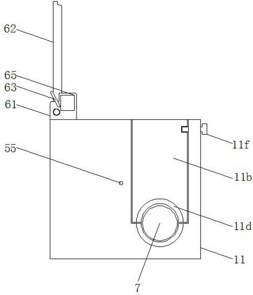
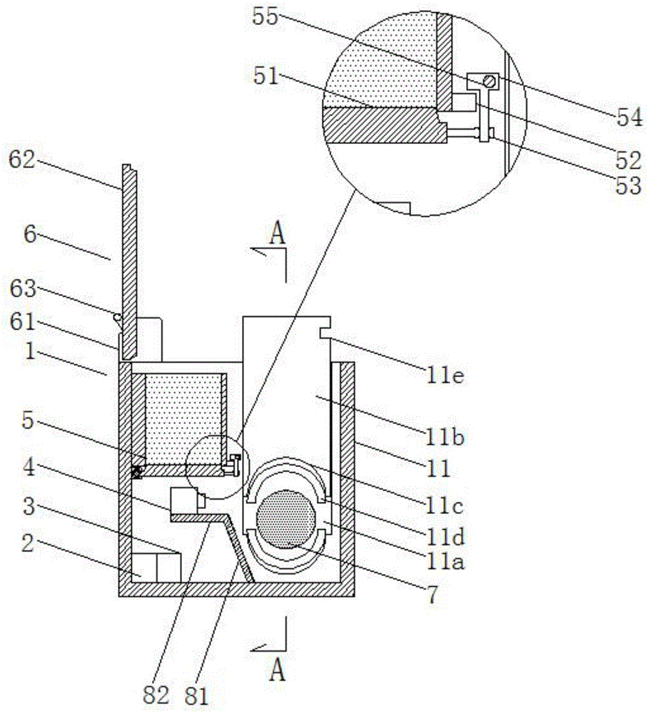
[0040] A cable fire protection device, characterized in that: it includes a horizontally arranged pipe 11 for covering cables;
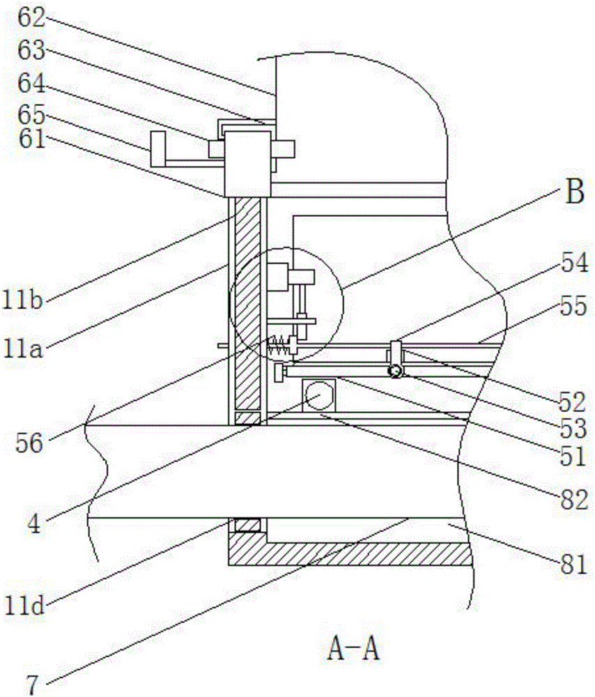
[0041] The pipe 11 is a hollow pipe with an open upper end, a pair of side walls corresponding to the length direction of the pipe 11 are provided with a downwardly disposed rectangular slot 11a, and a rectangular insert 11b is inserted in the rectangular slot 11a. The lower horizontal sides of the rectangular board 11b and the rectangular slot 11a are symmetrically provided with a semicircular groove 11c for clamping the cable 7;
[0042] A temperature sensor 2 is provided behind the lower bottom of the pipeline 11, and the temperature sensor 2 is electrically connected to a control device 3, and the control device 3 is also electrically connected to at least one automatic fire extinguisher 4, and the nozzle of the automatic fire extinguisher 4 is provided with a There is a solenoid valve electrically connected to the control device 3;
[0043]The top of the rear wall of the pipeline 11 is provided with a discharge trough 5 along the length direction of the pipeline 11. The upper and lower ends of the discharge trough 5 are open and set, and the bottom of the rear end surface of the discharge chute 5 is hinged for sealing. The bottom plate 51 at the lower end of the discharge chute 5 is filled with a sand layer, and the lower edge of the front end of the discharge chute 5 is provided with at least two stoppers 52, the front of the bottom plate 51 is in contact with the stopper. A rotating shaft 53 is provided at the corresponding position of the block 52, and each rotating shaft 53 is hinged with a claw 54 for clamping on the top of the block 52, and a connecting rod 55 is connected between the claws 54. The rod 55 passes through any side wall of the pipeline 11, and the connecting rod 55 is also provided with a retaining ring 55a near the side wall of the pipe 11 at a position of 10mm-100mm, and the connecting rod 55 is located on the side wall of the pipe 11 and the retaining ring 55a The part between is also wound with a compression spring 56, and a reduction motor 57 is also provided on the side wall of the pipeline 11, and a screw rod 58 is driven and connected to the bottom of the reduction motor 57, and a spiral tube 59 is arranged below the screw rod 58. , the outer circumference of the spiral tube 59 is rectangular, the lower end of the spiral tube 59 is clamped inside the retaining ring 55a, the side wall of the pipeline 11 is also provided with a limit rod 11g, and the limit rod 11g is provided with a The limit hole 11h fitted on the outer periphery of the spiral tube 59;
[0044] A pair of lugs 61 are respectively provided behind the upper end surfaces of the pair of side walls of the pipeline 11, and a cover plate 62 that matches the upper end surface of the pipeline 11 is hinged behind the pair of lugs 61, and each lug 61 is also provided with a cover plate 62. The torsion spring 63 that drives the cover plate 62 to turn forward, and a permanent magnet 64 is slidably inserted in the front of any lug 61 along the length direction of the pipe 11, and the permanent magnet 64 is clamped on the cover In front of the plate 62, an electromagnet 65 cooperating with the permanent magnet 64 is provided outside the lug 61;
[0045] Described reduction motor 57, electromagnet 65 are electrically connected with control device 3 respectively, and the solenoid valve of described temperature sensor 2, control device 3, automatic fire extinguisher 4, reduction motor 57, electromagnet 65 are all powered by a rechargeable power supply;
[0046] The middle part of the bottom plate of the pipeline 11 is provided with a vertical plate 81 whose height is not lower than that of the cable 7 , and a horizontal plate 82 is also provided behind the upper edge of the vertical plate 81 .
[0047] Further, a pair of semicircular fireproof sealing rings 11d are interposed between the inner wall of the semicircular groove 11c and the cable 7 .
[0048] Further, the front and rear end surfaces of the rectangular slot 11a and the rectangular plug-in plate 11b are pointed surfaces.
[0049] Further, a socket 11e is provided on the front end of the rectangular board 11b, and the front wall of the pipe 11 is screwed with a fixing bolt 11f that fits with the socket 11e and fixes the rectangular board 11b.
[0050] Further, the automatic fire extinguishers 4 are equally spaced on the horizontal plate 82 .
[0051] Further, the control device 3 at least includes a wireless transmission module, and the wireless transmission module is connected to the main station server or the mobile terminal in communication.
[0052] A method for using a cable fire prevention device, characterized in that it includes the following steps:
[0053] Step 1, call the police:
[0054] When the temperature sensor 2 detects that the ambient temperature reaches or exceeds T 1 , the temperature sensor 2 transmits the temperature signal to the control device 3, and the control device 3 controls the wireless transmitting module to transmit a distress signal for alarm, and the master station server or mobile terminal dispatches professionals after receiving the signal come to check;
[0055] Step 2, automatic fire extinguishing:
[0056] When the temperature sensor 2 detects that the ambient temperature reaches or exceeds T 2 , the temperature sensor 2 transmits the temperature signal to the control device 3, and the control device 3 controls the electromagnetic valve of the automatic fire extinguisher 4 to open, and the automatic fire extinguisher 4 sprays a fire extinguishing agent to extinguish the fire;
[0057] Step three, burial and sealing:
[0058] When the temperature sensor 2 detects that the ambient temperature reaches or exceeds T 2 and last for t 1 After a period of time, the control device 3 controls the geared motor 57 to drive the screw mandrel 58 to rotate. Since the screw tube 59 cannot rotate due to the limitation of the limiting hole 11h, the screw tube 59 is positioned on the screw mandrel. 58 to step upwards, when the coil 59 is separated from the stop ring 55a, the compression spring 56 drives the connecting rod 55 to move inward, and the end of the connecting rod 55 slides out from the pipe 11 , the connecting rod 55 drives the hook 54 to slip off from the block 52, the bottom plate 51 opens downwards and abuts on the horizontal plate 82, the sand layer is discharged and the cable is buried to achieve Flame retardant effect;
[0059] The control device 3 controls the electromagnet 65 to energize and attract the permanent magnet 64, and the permanent magnet 64 moves outward until the permanent magnet 64 is out of contact with the cover plate 62, and the cover plate 62 is affected by the The torsion spring 63 is driven to turn forward and cover the upper end surface of the pipe 11, so that the pipe 11 is closed and the external air is isolated so as to achieve a flame retardant effect.
[0060] Further, the T 2 greater than the T 1.
[0061] Further, in step 2, the control device 3 controls a remote control sending module to send a trip signal, and a remote control receiver receives the trip signal, and the output of the remote control receiver is connected to the shunt trip coil circuit of the circuit breaker or connected to the leakage current The test button switch of the protector generates the tripping action of the circuit breaker or leakage protector accordingly.