A high-efficiency garbage separator
A technology for separators and garbage, applied to centrifuges, centrifuges with rotating drums, etc., can solve problems such as low degree of automation, insufficient output torque, and poor separation effect, achieving obvious air leakage and high output torque Large, good separation effect
- Summary
- Abstract
- Description
- Claims
- Application Information
AI Technical Summary
Problems solved by technology
Method used
Image
Examples
Embodiment 1
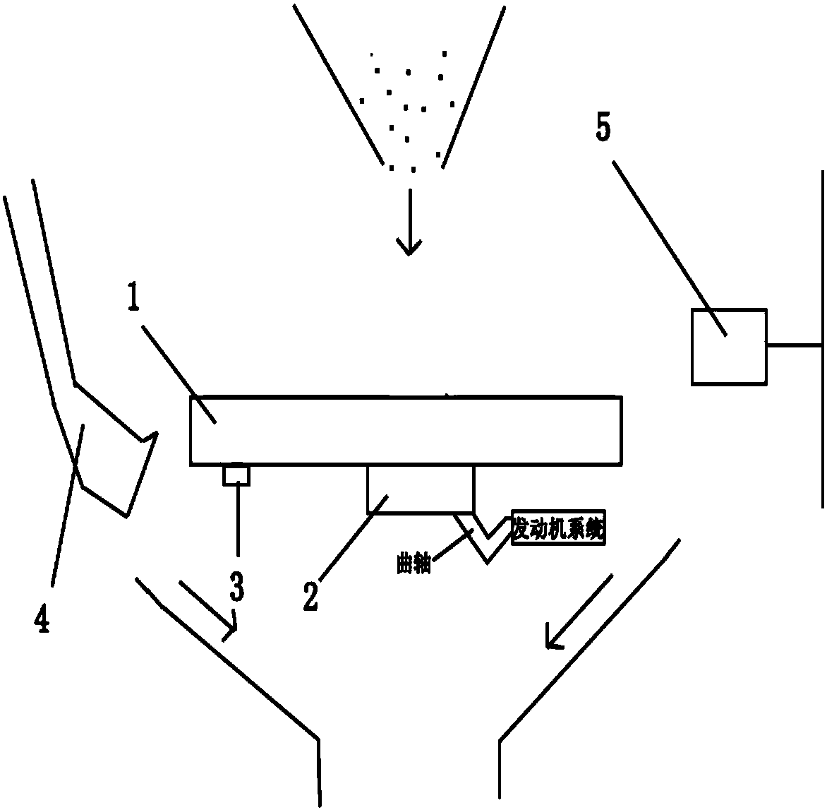
[0021] Such as figure 1A high-efficiency garbage separator shown includes a separation turntable 1, a transmission round block 2, a gravity sensor 3, a mechanical arm receiving bucket 4, a propeller 5 and an engine system, and the transmission round block 2 and the gravity sensor 3 are fixed on the Below the separation turntable 1, the propeller 5 and the mechanical arm receiving bucket 4 are respectively located on both sides of the separation turntable 1; the garbage falls into the separation turntable 1 from the feeding port, and the small garbage is separated outwards and falls into the separation turntable under the action of centrifugal force. At the outlet below the turntable 1, large garbage accumulates on the separation turntable 1; when the weight of the large garbage accumulation exceeds the set value, the gravity sensor 3 sends a signal to the controller, driving the propeller 5 to push in the direction of the separation turntable 1, At the same time, the mechanica...
Embodiment 2
[0032] Such as figure 1 A high-efficiency garbage separator shown includes a separation turntable 1, a transmission round block 2, a gravity sensor 3, a mechanical arm receiving bucket 4, a propeller 5 and an engine system, and the transmission round block 2 and the gravity sensor 3 are fixed on the Below the separation turntable 1, the propeller 5 and the mechanical arm receiving bucket 4 are respectively located on both sides of the separation turntable 1; the garbage falls into the separation turntable 1 from the feeding port, and the small garbage is separated outwards and falls into the separation turntable under the action of centrifugal force. At the outlet below the turntable 1, large garbage accumulates on the separation turntable 1; when the weight of the large garbage accumulation exceeds the set value, the gravity sensor 3 sends a signal to the controller, driving the propeller 5 to push in the direction of the separation turntable 1, At the same time, the mechanic...
Embodiment 3
[0043] Such as figure 1 A high-efficiency garbage separator shown includes a separation turntable 1, a transmission round block 2, a gravity sensor 3, a mechanical arm receiving bucket 4, a propeller 5 and an engine system, and the transmission round block 2 and the gravity sensor 3 are fixed on the Below the separation turntable 1, the propeller 5 and the mechanical arm receiving bucket 4 are respectively located on both sides of the separation turntable 1; the garbage falls into the separation turntable 1 from the feeding port, and the small garbage is separated outwards and falls into the separation turntable under the action of centrifugal force. At the outlet below the turntable 1, large garbage accumulates on the separation turntable 1; when the weight of the large garbage accumulation exceeds the set value, the gravity sensor 3 sends a signal to the controller, driving the propeller 5 to push in the direction of the separation turntable 1, At the same time, the mechanic...
PUM
 Abstract
Description
Claims
Application Information
 - R&D
- Intellectual Property
- Life Sciences
- Materials
- Tech Scout
- Unparalleled Data Quality
- Higher Quality Content
- 60% Fewer Hallucinations
Browse by: Latest US Patents, China's latest patents, Technical Efficacy Thesaurus, Application Domain, Technology Topic, Popular Technical Reports.
© 2025 PatSnap. All rights reserved.Legal|Privacy policy|Modern Slavery Act Transparency Statement|Sitemap|About US| Contact US: help@patsnap.com


