A rotary mechanism for a working turntable

A technology of slewing mechanism and turntable, which is applied in the direction of metal processing machinery parts, manufacturing tools, metal processing equipment, etc., can solve the problems of unstable speed change, strong impact, affecting the stability and service life of the working turntable, etc., and achieves stable speed change , The operation takes up less space and the effect of improving the service life

CN105773183BActive Publication Date: 2018-02-23知普企望(温州)电力技术研究院有限公司
8 Cites 0 Cited by

Patent Information

Authority / Receiving Office
CN · China
Patent Type
Patents(China)
Current Assignee / Owner
Publication Date
2018-02-23

Smart Images

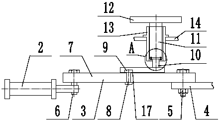
  • Figure 1
    Figure 1
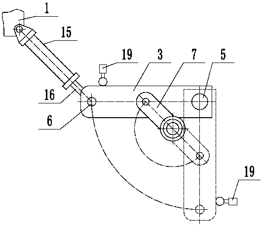
  • Figure 2
    Figure 2
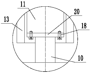
  • Figure 3
    Figure 3
Patent Text Reader

Abstract

The invention provides a swing mechanism for a turntable and belongs to the technical field of mechanical equipment. The swing mechanism comprises a first swing rod, a supporting shaft, a second swing rod and an output rotary shaft. One end of the first swing rod is hinged to a first supporting plate through the supporting shaft. The rear end of a cylinder body of a drive air cylinder is hinged to a rack. The front end of a piston rod is hinged to the other end of the first swing rod through a first pin shaft. A second pin shaft is mounted at the middle end of the first swing rod. A rolling wheel is rotationally arranged above the second pin shaft. A rolling wheel groove is formed in one end of the second swing rod. The rolling wheel is located in the rolling wheel groove. The other end of the second swing rod is connected with a transition shaft. A connecting disc is arranged at the upper end of the transition shaft and coaxially connected with the output rotary shaft through fastening screws. The output rotary shaft is rotationally arranged on a rotary shaft sleeve. The turntable is coaxially and concentrically arranged at the upper end of the output rotary shaft. The swinging angle of the first swing rod is 90 degrees. The swing mechanism for the turntable achieves the effects that the turntable is stable in speed change when being started or stopped, and the impact phenomenon is avoided.
Need to check novelty before this filing date? Find Prior Art

Description

technical field

[0001] The invention relates to the technical field of mechanical equipment, in particular to a rotating mechanism of a working turntable. Background technique

[0002] CNC machine tool is the abbreviation of numerical control machine tool, which is an automatic machine tool equipped with a program control system. The control system can logically process programs with control codes or other symbolic instructions, decode them, express them in coded numbers, and input them into the numerical control device through the information carrier. After calculation and processing, various control signals are sent by the numerical control device to control the movement of the machine tool, and the parts are automatically processed according to the shape and size required by the drawing. CNC machine tools solve complex, precise, small-batch, and multi-variety parts processing problems. It is a flexible, high-efficiency automatic machine tool that represents the developme...

Examples

Embodiment Construction

[0013] The present invention will be further described in detail below in conjunction with the accompanying drawings and examples. The following examples are explanations of the present invention and the present invention is not limited to the following examples.

[0014] Such as figure 1 , figure 2 and image 3 As shown, a rotary mechanism of a working turntable includes a frame 1, a drive cylinder 2, a first swing rod 3, a first support plate 4, a support shaft 5, a first pin shaft 6, a second swing rod 7, a second Pin shaft 8, roller 9, transition shaft 10, output shaft 11, working turntable 12, shaft sleeve 13, second support plate 14, one end of the first swing link 3 is hinged on the first support plate 4 through the support shaft 5 , the first support plate 4 is fixed on the frame 1. Described drive cylinder 2 comprises cylinder body 15 and piston rod 16, and the rear end of described cylinder body 15 is hinged on the frame 1, and the front end of described piston r...