Real-time monitoring device and method for cutting force signals in machining process

A processing process and real-time monitoring technology, applied in metal processing equipment, metal processing machinery parts, manufacturing tools, etc., can solve the problems of time waste, not easy to carry, complicated connection, etc., and achieve simple and convenient use, strong versatility and practicality strong effect

Active Publication Date: 2016-07-20
TIANJIN UNIV
View PDF8 Cites 1 Cited by
  • Summary
  • Abstract
  • Description
  • Claims
  • Application Information

AI Technical Summary

Problems solved by technology

During the collection process, there are many instruments, the connection is complicated, and it is not easy to carry, which brings a lot of unnecessary time waste to the user; the installation of the force measuring instrument is restricted by external factors such as processing conditions and workpiece size

Method used


Image

  • Real-time monitoring device and method for cutting force signals in machining process
  • Real-time monitoring device and method for cutting force signals in machining process
  • Real-time monitoring device and method for cutting force signals in machining process

Examples


Embodiment Construction

[0016] The present invention will be further described in detail below in combination with specific embodiments.

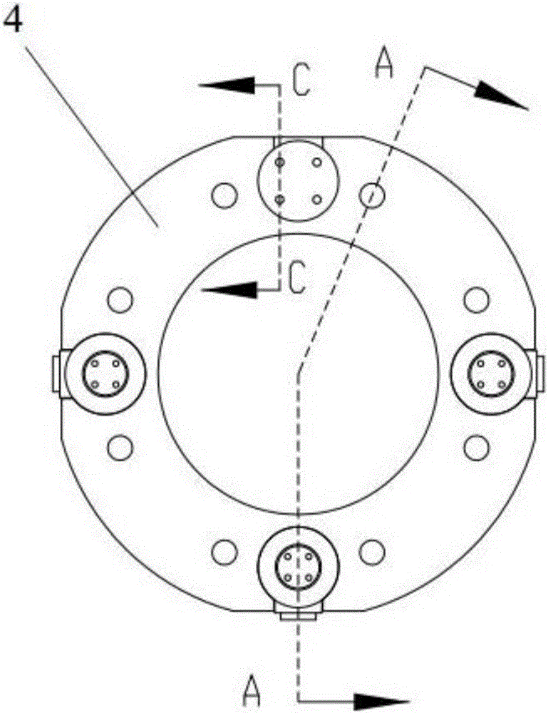
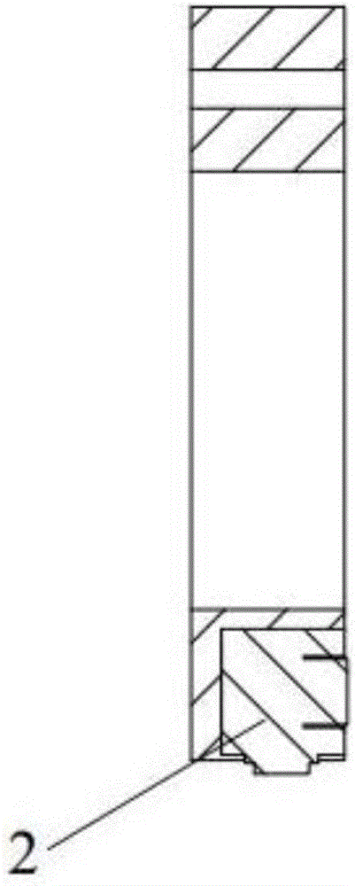
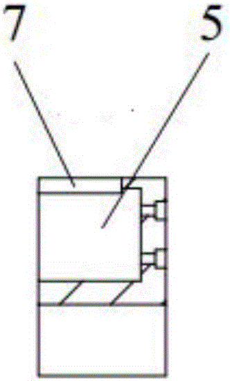
[0017] As shown in the drawings, the present invention is a real-time monitoring device for cutting force signals during machining, which includes an annular force-measuring device 4, and the annular force-measuring device 4 includes a body with a hole in the middle, and the The annular force measuring device 4 is set on the electric spindle body 1 through the middle opening and clamped and fixed between the electric spindle flange 6 and the fixed flange 3 of the equipment. The clamping and fixing can be done through the ring force measuring device 4, the electric The main shaft flange 6 and the fixed flange 3 of the equipment are fixed by bolts. On the body, there are four force sensor placement holes 5 at intervals of 90 degrees in the same circumferential direction, and a force sensor placement hole 5 is fixed in each force sensor placement hole 5. A three-way ...


PUM


Abstract

The invention discloses a real-time monitoring device and method for cutting force signals in the machining process. The device comprises an annular force measuring device. The annular force measuring device comprises a body with a hole formed in the middle. The annular force measuring device is arranged on a motorized spindle body in a sleeving manner through the middle hole and clamped and fixed between a motorized spindle flange and an equipment fixing flange. Four force sensor containing holes are formed in the same circumferential direction of the body at the interval of 90 degrees. A three-way force sensor is fixed in each force sensor containing hole. A groove where a signal line of the three-way force sensor penetrates is formed in the outer side of each force sensor containing hole. The signal line of each three-way force sensor is sequentially connected with a front amplifier, a data collection card and a computer. The real-time monitoring device is simple and reliable in structure and high in universality.

Description

technical field [0001] The invention relates to the field of real-time monitoring and control of processing status, in particular to a real-time monitoring device for cutting force signals during processing. Background technique [0002] At present, with the higher and higher requirements for machining and manufacturing precision, the intelligent manufacturing system that monitors and controls the machining status in real time by collecting machining process signals has gradually attracted attention, among which the cutting force signal can best reflect the machining process status; machining cutting force signal data The acquisition is generally carried out by the dynamic force measuring instrument of Kisler Company, and then the force signal of the charge is transmitted to the charge amplifier through the transmission line and converted into a voltage signal. These data are stored in the computer. During the collection process, there are many instruments, the connection i...

Claims


Application Information

Patent Timeline
Patent Type & Authority Applications(China)
IPC IPC(8): B23Q17/09
CPCB23Q17/0952
Inventor 王国锋宋庆月吴丽蕊杨星焕张全彪
Owner TIANJIN UNIV
Why Eureka
Try Eureka