U-shaped pin pull-out device

A kind of puller, U-shaped technology, applied in the direction of hand-held tools, manufacturing tools, etc., can solve the problems of easy injury, high labor intensity of operators, complicated pullout process, etc., to prevent bruises and improve the pullout effect Effect

Inactive Publication Date: 2016-07-20
朱鹏飞
View PDF0 Cites 2 Cited by
  • Summary
  • Abstract
  • Description
  • Claims
  • Application Information

AI Technical Summary

Problems solved by technology

However, when the temporary pipeline or terminal equipment such as pneumatic drills and picks are used up, the pipeline must be removed or the terminal equipment recovered in time. At this time, it is inevitable to encounter the problem of difficult removal of U-shaped pins
[0003] When removing the U-shaped pins, most of them are pulled out by using a screwdriver to pry them together with a pliers and a hammer to knock them out. Because some U-shaped pins are tightly fixed or bent and deformed during use, the removal often fails, and the screwdriver is also used. Bending deformation often occurs during the prying process; hitting with a hammer is not only easy to injure hands, but also easily damages ferrules and joints; at the same time, the labor intensity of operators is high, the process of pulling pins is complicated, low in efficiency, prone to bruises, scratches, etc. Happening

Method used


Image

  • U-shaped pin pull-out device
  • U-shaped pin pull-out device
  • U-shaped pin pull-out device

Examples


Embodiment 1

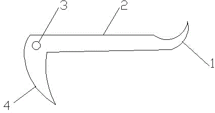
[0016] Embodiment one: if figure 1 As shown, a U-shaped pin puller includes a strip steel plate 2, and one end of the strip steel plate 2 is set as a small elbow 1 bent upward. The arcs on the left and right sides of the small elbow 1 intersect at the tip, which is conducive to the insertion of the present invention into the contact between the U-shaped pin and the fixture.

Embodiment 2

[0017] Embodiment two: if figure 1 As shown, on the basis of the first embodiment, the other end of the strip steel plate 2 is set as a large elbow 4 bent downward. The arcs on the left and right sides of the large elbow 4 intersect at the tip, which is conducive to the insertion of the present invention into the contact between the U-shaped pin and the fixture.

Embodiment 3

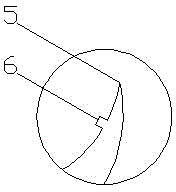
[0018] Embodiment three: as figure 2 As shown, on the basis of the first or second embodiment, a protrusion 5 is provided on the left side of the small elbow 1 near the tip 5 .


PUM


Abstract

Disclosed is a U-shaped pin pull-out device. The U-shaped pin pull-out device comprises a strip-shaped steel plate. A small elbow which is upwards bent is arranged at one end of the strip-shaped steel plate, and is mainly used for pulling small U-shaped pins out. A large elbow which is downwards bent is arranged at the other end of the strip-shaped steel plate. A protrusion is arranged on the portion, close to the sharp portion, of the left side of the small elbow, and a protrusion is arranged on the portion, close to the sharp portion, of the right side of the large elbow. The steel plate is a stainless steel plate. Due to the facts that existing methods that U-shaped pins are pried by a screwdriver, a vice is matched with the screwdriver to pull the U-shaped pins out, and the U-shaped pins are knocked by a hammer can be changed, and the U-shaped pins can be pulled out by a special tool, the pull-out effect can be effectively improved, and the situation that a worker is bruised or scratched can be avoided.

Description

technical field [0001] The invention relates to a pulling tool, in particular to a U-shaped pin puller. Background technique [0002] The connection between underground temporary hydraulic pipes, air pipes, water pipes and other rubber hoses, and the connection between the above-mentioned pipelines and terminal equipment is mostly realized by ferrule-type straight-through and quick connectors fixed at both ends of the rubber hose. When ferrule-type straight-through and fast Once the joints are connected, they must be secured with U-shaped pins. When it is fixed with U-shaped pin, it is very convenient to insert, and after insertion, it can be fixed in place by lightly tapping with a tool. However, when temporary pipelines or terminal equipment such as pneumatic drills and pneumatic picks are used up, it is necessary to remove the pipeline or recycle the terminal equipment in time. At this time, it is inevitable to encounter the problem of difficult removal of U-shaped pins....

Claims


Application Information

Patent Timeline
Patent Type & Authority Applications(China)
IPC IPC(8): B25B27/02
Inventor 朱鹏飞冯秀强潘段玲
Owner 朱鹏飞
Why Eureka
Try Eureka