High-precision micro-gripper

A micro-clamping and high-precision technology, applied in the field of micro-mechanical assembly tools and micro-grippers, can solve the problem that the clamped parts are easily damaged, the control accuracy of the micro-force of the micro-gripper is low, and the operation accuracy is affected, etc. problems, to achieve the effect of improving force adjustment accuracy, low power consumption, and high precision retention.

Inactive Publication Date: 2016-07-20
陈昊哲
View PDF8 Cites 3 Cited by
  • Summary
  • Abstract
  • Description
  • Claims
  • Application Information

AI Technical Summary

Problems solved by technology

[0004] 1) The control accuracy of the clamping force of the micro-gripper is low, and the clamped parts are easily damaged;
[0005] 2) The power source of the micro gripper is generally a device with a heat source such as a linear motor or thermal expansion, and thermal deformation factors affect the operation accuracy

Method used


Image

  • High-precision micro-gripper
  • High-precision micro-gripper
  • High-precision micro-gripper

Examples


Embodiment Construction

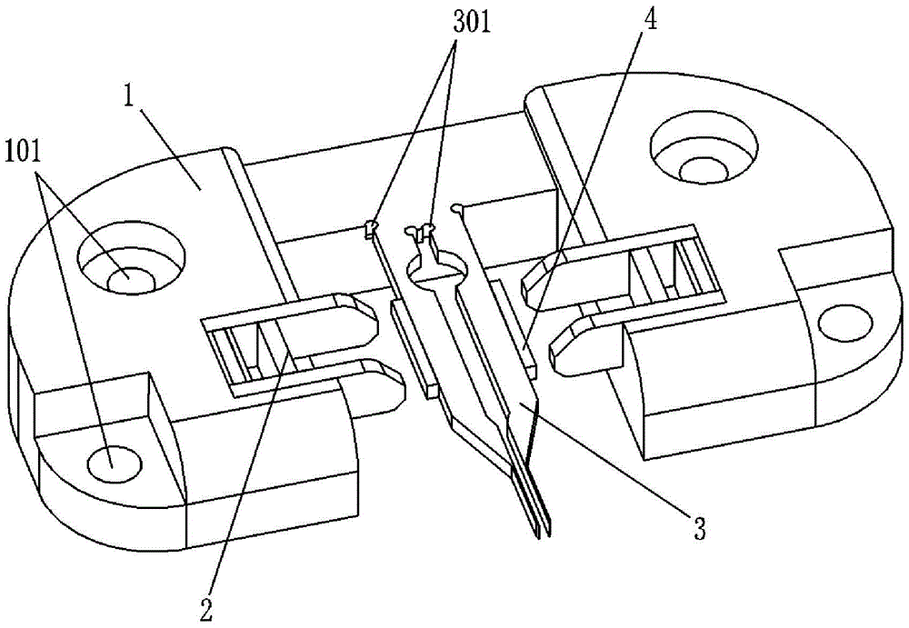
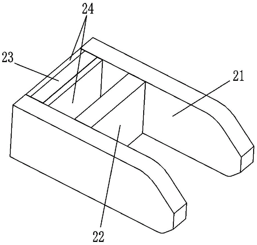
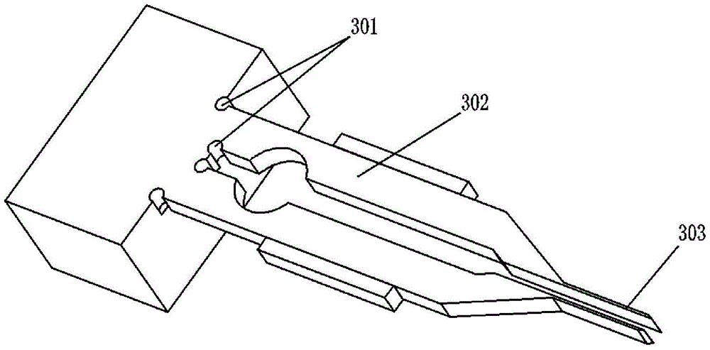
[0016] refer to figure 1 , figure 2 and image 3 , the high-precision micro-gripper of the present invention includes a platform base 1, a micro-force driver 2, a micro-clamping pliers 3 and a force magnet 4; the platform base 1 has a symmetrical structure, and is provided with symmetrically distributed screw holes 101; The micro-force driver 2 is symmetrically arranged on the platform base 1, and the micro-clamping forceps 3 are arranged at the symmetrical central plane of the platform base 1; the micro-force driver 2 includes two piezoelectric ceramic sheets 24, located The giant magnetostrictive sheet 23 between sheet piezoelectric ceramic sheet 24, the permanent magnet 22 that arranges parallel with giant magnetostrictive sheet 23, be positioned at giant magnetostrictive sheet 23, piezoelectric ceramic sheet 24 and permanent magnet 22 two ends and Two magnetic fixed yokes 21 for clamping the giant magnetostrictive sheet 23 and the permanent magnet 22; the micro-clamping...


PUM


Abstract

The invention discloses a high-precision micro-gripper. The high-precision micro-gripper comprises a platform base, micro-force drivers, micro gripping pliers and a stress magnet. The platform base is of a symmetrical structure and provided with symmetrically-distributed screw holes. The micro-force drivers are arranged on the platform base symmetrically. The micro gripping pliers are arranged on the symmetrical center face of the platform base. Each micro-force driver comprises two piezoelectric ceramic pieces, a super-magnetic expansion piece located between the two piezoelectric ceramic pieces, a permanent magnet arranged parallel to the super-magnetic expansion piece and two magnetic fixing yokes. The two magnetic fixing yokes are located at the two ends of the super-magnetic expansion piece, the piezoelectric ceramic pieces and the permanent magnet and grip the super-magnetic expansion piece and the permanent magnet. According to the high-precision micro-gripper, the controlled precision of the magnitude of the gripping micro force of the micro-gripper is high. In addition, the power consumption is low, the amount of emitted heat is small, and the precision stability is good.

Description

【Technical field】 [0001] The invention relates to the technical field of micromechanical assembly tools, especially the technical field of micro grippers. 【Background technique】 [0002] The rapid development of microelectromechanical systems (MEMS) has changed from the field of "microelectronics-mechanical" to "micromechanical-electronics". There are more and more tiny mechanical structural parts in MEMS devices, which are becoming more and more complex. In particular, automated micromechanical assembly poses enormous challenges. [0003] The assembly of traditional micromechanical parts relies on microgrippers, which are widely used, but there are the following problems: [0004] 1) The control accuracy of the clamping force of the micro-gripper is low, and the clamped parts are easily damaged; [0005] 2) The power source of the micro gripper is generally a device with a heat source such as a linear motor or thermal expansion, and thermal deformation factors affect the ...

Claims


Application Information

Patent Timeline
Patent Type & Authority Applications(China)
IPC IPC(8): B25J7/00H02N2/00
CPCB25J7/00H02N2/0055
Inventor 陈昊哲
Owner 陈昊哲
Why Eureka
Try Eureka