Power generation type bus handle

A handlebar, power generation technology, applied in the directions of generators/motors, electrical components, vehicle components, etc., can solve the problem of difficult to locate the pull ring and hold the handle of the sling pull ring, affecting the passenger's satisfaction with the bus ride, and the difficulty of passengers. Problems such as positioning the crossbar and holding the crossbar to achieve the effect of improving body balance, saving space and low manufacturing cost

Active Publication Date: 2016-07-20
WUHAN UNIV OF TECH
View PDF7 Cites 11 Cited by
  • Summary
  • Abstract
  • Description
  • Claims
  • Application Information

AI Technical Summary

Problems solved by technology

[0004] 1. Set the traditional sling pull ring handle, which generally consists of three parts, the upper ring, the rope and the lower pull ring. The upper ring is fixed on the bus bar, and the rope connects the upper ring and the lower pull ring. , Passengers hold the lower pull ring with their hands. When the bus brakes or starts, due to the softness of the rope, the passengers cannot maintain their body balance well even if they hold the pull rod tightly, and they will always lean forward or backward; at the same time, at night When taking the bus, due to the lack of light in the car, it is difficult for passengers to accurately locate the pull ring and hold the handle of the strap pull ring in time, which seriously affects the passengers' satisfaction with the bus ride
[0005] 2. There are no handles. There are no handles in the buses in some cities. Passengers can maintain their balance by holding on to the crossbar on the bus. Due to the uneven height of passengers, the influence of the crossbar at the same height cannot satisfy all passengers. Seriously It affects the ride comfort of passengers; at the same time, when taking the bus at night, the problem that passengers are difficult to accurately position and hold the crossbar in time still exists
This kind of bus handle only realizes power generation and collects electricity through the principle of piezoelectricity, and does not involve how to rationally use the collected electricity. The entire scheme design is not complete.

Method used


Image

  • Power generation type bus handle
  • Power generation type bus handle
  • Power generation type bus handle

Examples


Embodiment Construction

[0031] The principles and features of the present invention are described below in conjunction with the accompanying drawings, and the examples given are only used to explain the present invention, and are not intended to limit the scope of the present invention.

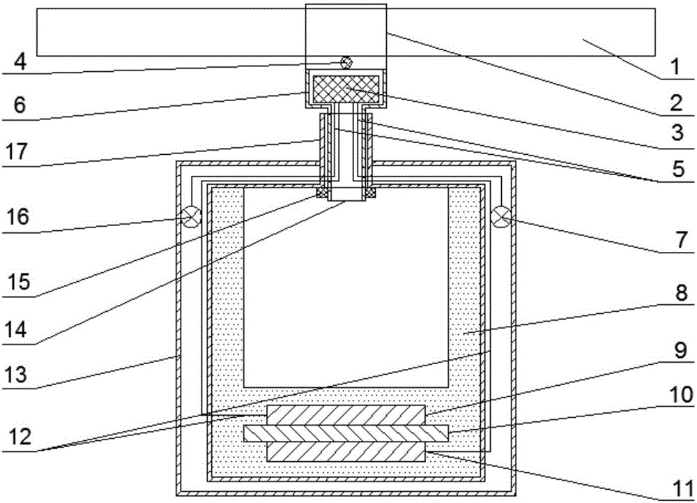
[0032] The power generation type bus handle provided by the invention, as figure 1 As shown, it consists of an upper fixed part and a lower pull ring part.

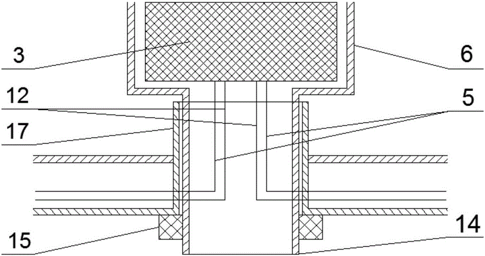
[0033] The upper fixing part is mainly composed of a fixing sleeve 2 , a cavity 6 and a rechargeable battery 3 . The fixed sleeve 2, the cavity 6, and the end hollow cylinder 14 are a whole. The fixing part fixes the upper part on the crossbar 1 of the bus as a whole through the bolt 4, and the cavity 6 is used to place the rechargeable battery 3. In order to prevent the rechargeable battery 3 from shifting, the bottom of the rechargeable battery 3 is glued to the bottom of the cavity 6 with glue. face.

[0034] The lower pull ring part is mainly composed of...


PUM


Abstract

The invention relates to a power generation type bus handle, comprising a fixed part and a pull ring part, wherein a rechargeable battery (3) is arranged at the upper part of the fixed part, a piezoelectric device and a light-emitting diode (LED) lamp are arranged at the lower part of the pull ring part, and the fixed part and the pull ring part are organically connected into a whole; the piezoelectric device is used for converting the mechanical energy of the body of a passenger into electric energy so as to enable the LED lamp to be on, and enabling the produced extra electric energy to be stored into the rechargeable battery (3) in time. According to the power generation type bus handle, a connecting way between a rope belt and a cylinder is replaced by another connecting way between two cylinders, so that the bus handle is beneficial to improving the body balance of the passenger who takes a bus, and the comfort of the passenger who takes the bus is enhanced; the piezoelectric power generation device is used for converting the mechanical energy of the passenger caused by inertia into the electric energy, so that the bus handle is energy-saving and convenient; an LED lighting circuit is used for converting the electric energy into light energy, so that the passenger can conveniently, rapidly and accurately locate the position of a pull ring, greater convenience is brought to the passenger, and the safety of the passenger who takes the bus is also improved; the whole handle is small in structure and high in practicality.

Description

technical field [0001] The present invention relates to the field of electric power system, more specifically, relates to the reasonable design of the bus handle, based on the concept of comfort, convenience, safety and energy saving for passengers on the bus, the final designed product can achieve the effect of taking into account the above concepts . Background technique [0002] With the rapid development of society and the improvement of people's living standards, public transportation has become an important development field in today's era, and it is also one of the important ways people choose to travel. At present, the bus facilities in major cities are relatively sound, but the seats on the bus are difficult to meet the increasing number of people traveling by bus and subway. When there are many passengers, most passengers can only hold the handle on the bus to maintain their body balance. The existing handle has the problem of unstable grip, and it is difficult fo...

Claims


Application Information

Patent Timeline
Patent Type & Authority Applications(China)
IPC IPC(8): B60N3/02B60Q3/02H02N2/18
CPCB60N3/02H02N2/18H02N2/181
Inventor 曹菁菁万立成
Owner WUHAN UNIV OF TECH
Why Eureka
Try Eureka