Inverted take-up device and inverted take-up method

An inverted wire take-up device, which is applied in the field of inverted wire take-up devices, can solve problems such as low wire take-up efficiency and inconvenient production, reduce the probability of damage or breakage, simplify the replacement process, improve wire take-up efficiency and The effect of production efficiency

Inactive Publication Date: 2016-07-20
NANTONG HUIFENG ELECTRONICS TECH
View PDF9 Cites 4 Cited by
  • Summary
  • Abstract
  • Description
  • Claims
  • Application Information

AI Technical Summary

Problems solved by technology

[0005] The technical problem to be solved by the present invention is that in the prior art, the winding reel and the take-up reel of the wire take-up device are connected by the same driving member, so that the winding efficiency is low and the production is inconvenient. The take-up device is driven separately by two unlinked driving parts to realize that the speed of the take-up device can be adjusted independently of the winding reel, thereby improving the take-up efficiency and reducing the cost of the take-up device

Method used


Image

  • Inverted take-up device and inverted take-up method
  • Inverted take-up device and inverted take-up method
  • Inverted take-up device and inverted take-up method

Examples


Embodiment 1

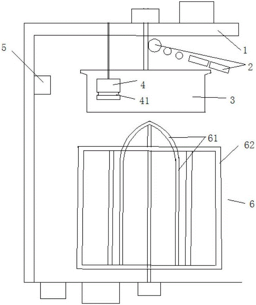
[0056] This embodiment provides an inverted wire take-up device, comprising:

[0057] Rack 1;

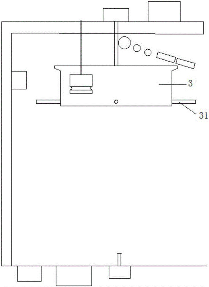
[0058] Winding reel 3, rotatable setting;

[0059] The first motor is used to drive the winding reel 3 to rotate;

[0060] The wire device 2 is used to guide the external wire into the winding reel 3, wind it on the winding reel 3, and drive the wire to fall;

[0061] The take-up basket 6 is rotatably arranged directly below the winding reel 3;

[0062] The second motor is used to drive the take-up basket 6 to rotate, and is not linked with the first motor;

[0063] The controller independently controls the actions of the first motor and the second motor.

[0064] In the above-mentioned inverted take-up device, the winding reel 3 and the take-up basket 6 are respectively driven by the first motor and the second motor, the first motor and the second motor are not set in linkage, and are independently controlled by the controller, The rotation speed of the take-up basket can be a...

Embodiment 2

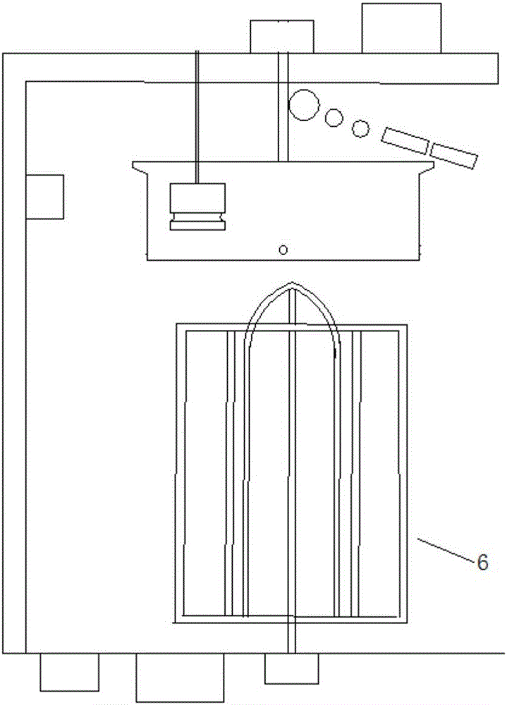
[0080] This embodiment provides a method for taking up a wire by an inverted wire take-up device, which includes the following steps:

[0081] S1: Drive the external wire into the winding reel 3 and wind it on the winding reel 3;

[0082] S2: drive the winding reel 3 to rotate;

[0083] S3: driving the take-up basket 6 to rotate independently of the winding reel 3;

[0084] S4: The wire is lowered from the winding reel 3 into the take-up basket 6 .

[0085] The take-up basket 6 rotates independently of the winding reel 3, so that the rotating speeds of the winding reel 3 and the take-up basket 6 can be controlled and adjusted separately, so the speed of the take-up basket 6 can be set to be greater than the speed of the winding reel 3, that is It is possible to make the coil diameter of the wire coiled in the wire basket 6 smaller than the wire coil diameter falling from the winding reel 3, the greater the rotation speed of the wire basket 6, the smaller the coil diameter of...


PUM


Abstract

The invention discloses an inverted take-up device. The inverted take-up device comprises a rack, a wire spool, a first motor, a wire guiding device, a take-up basket, a second motor and a controller, wherein the wire spool can be rotationally arranged; the first motor is used for driving the wire spool to rotate; the wire guiding device is used for guiding external wires to enter the wire spool and wind the wire spool, and driving the wires to fall off; the take-up basket is rotationally arranged under the wire spool; the second motor is used for driving the take-up basket to rotate and is not linked with the first motor; and the controller independently controls the first motor and the second motor to act.

Description

technical field [0001] The invention discloses an inverted wire take-up device and a method, belonging to the technical field of electromechanical equipment for metal products. Background technique [0002] The wire take-up device can also be called a wire winding machine or a wire take-up machine. During the production process, automatic winding technology is used to realize the function of wire winding, including horizontal wire take-up machines and inverted wire take-up machines. The take-up accuracy and stability of the inverted take-up machine are not as good as the horizontal take-up machine, but it has better economy, so it is usually used for the take-up of semi-finished products with large specifications and heavy weights. During the winding process, the winding reel of the inverted take-up machine rotates around the rotating shaft at a certain speed to continuously roll the wire into the winding reel and drop it onto the take-up rack in turn. Usually, the take-up s...

Claims


Application Information

Patent Timeline
Patent Type & Authority Applications(China)
IPC IPC(8): B65H54/10B65H63/00
CPCB65H54/10B65H63/00
Inventor 石明华蔡成俊陈健宋小波
Owner NANTONG HUIFENG ELECTRONICS TECH
Why Eureka
Try Eureka