
Collection mechanism of oil in concentrated liquid and oil-water separation device

A technology of oil-water separation device and collection mechanism, which can be applied to grease/oily substance/float removal device, water/sewage multi-stage treatment, heating water/sewage treatment, etc. It is very suitable for problems such as coating lines, and achieves the effect of improving oil removal efficiency and reducing oil removal costs.

Active Publication Date: 2018-05-08
AUTOMOTIVE ENG CORP +1
View PDF6 Cites 0 Cited by
  • Summary
  • Abstract
  • Description
  • Claims
  • Application Information

AI Technical Summary

Problems solved by technology

[0002] The pre-treatment of automobile painting is an important process line, and degreasing is the primary key process. In order to obtain good coating quality and meet the requirements of coating corrosion resistance and appearance decoration, it is necessary to separate oil and water from the degreasing liquid. The ultrafiltration membrane degreasing device has gradually been paid more and more attention to because of the relatively thorough degreasing, but there will be the following disadvantages when using the traditional degreasing liquid ultrafiltration membrane degreasing device: the ultrafiltration degreasing belongs to the method of circulating concentration, which increases the waste liquid. The concentration ratio is generally 30-40 times, and the final waste liquid is discharged as a whole and treated as waste liquid; the oil content in the degreasing liquid of the coating line is generally controlled at 2000-3000PPM, and the oil content in the concentrated waste liquid is only 10%- 20%, the degreasing liquid of the active ingredient is discharged as waste liquid, and at the same time increases the cost of waste treatment, so the method of ultrafiltration to remove oil is not suitable for the coating line

Method used


Image

  • Collection mechanism of oil in concentrated liquid and oil-water separation device
  • Collection mechanism of oil in concentrated liquid and oil-water separation device
  • Collection mechanism of oil in concentrated liquid and oil-water separation device

Examples


Embodiment Construction

[0018] The present invention will be described in further detail below in conjunction with the accompanying drawings and specific embodiments. It should be understood that the specific embodiments described here are only used to explain the present invention, not to limit the present invention.

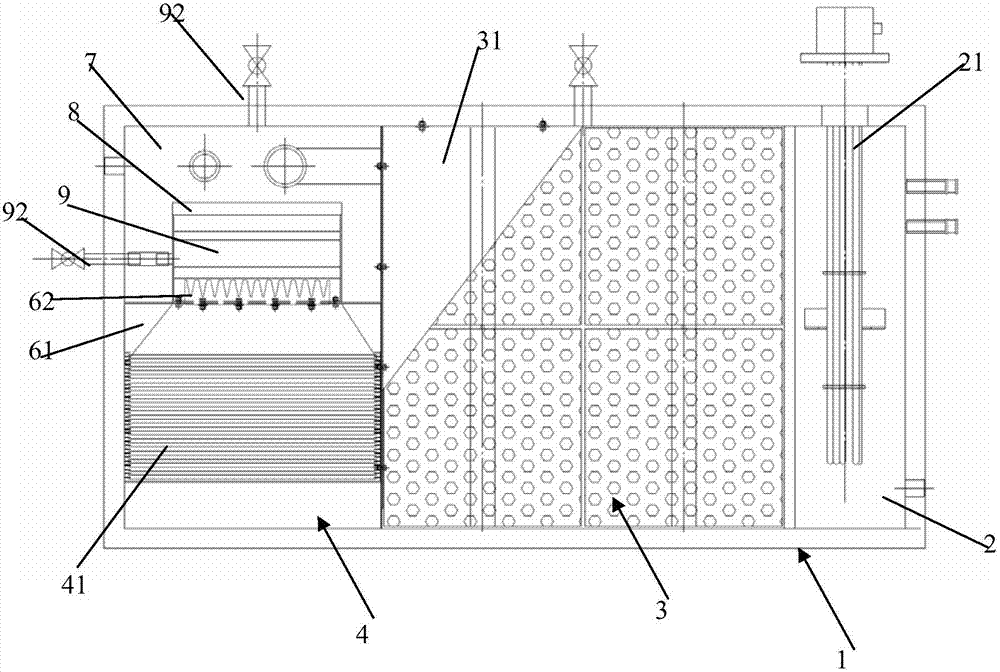
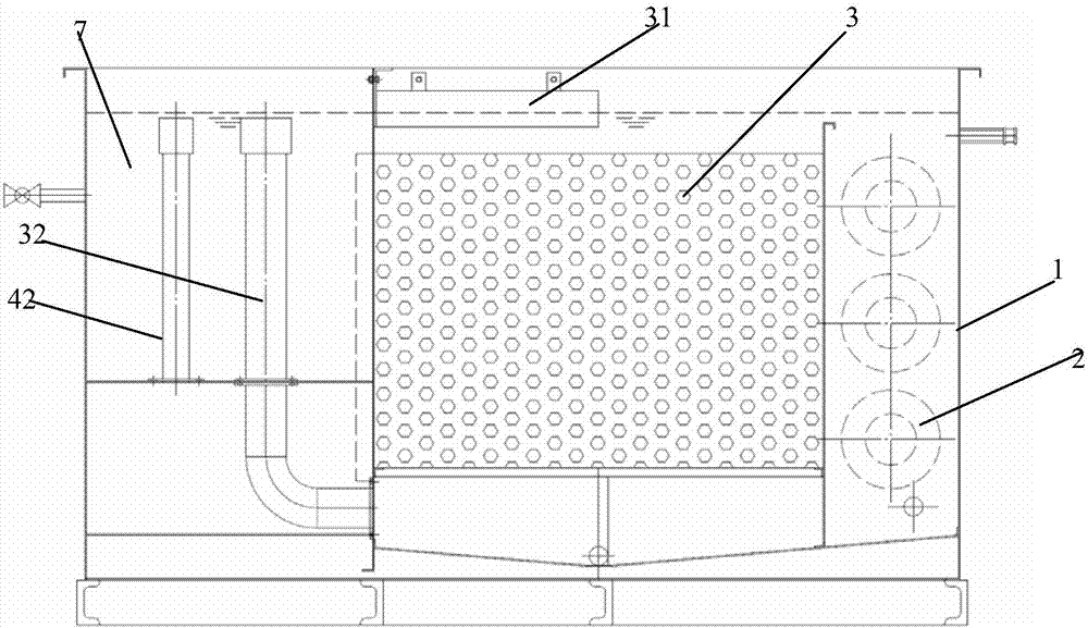
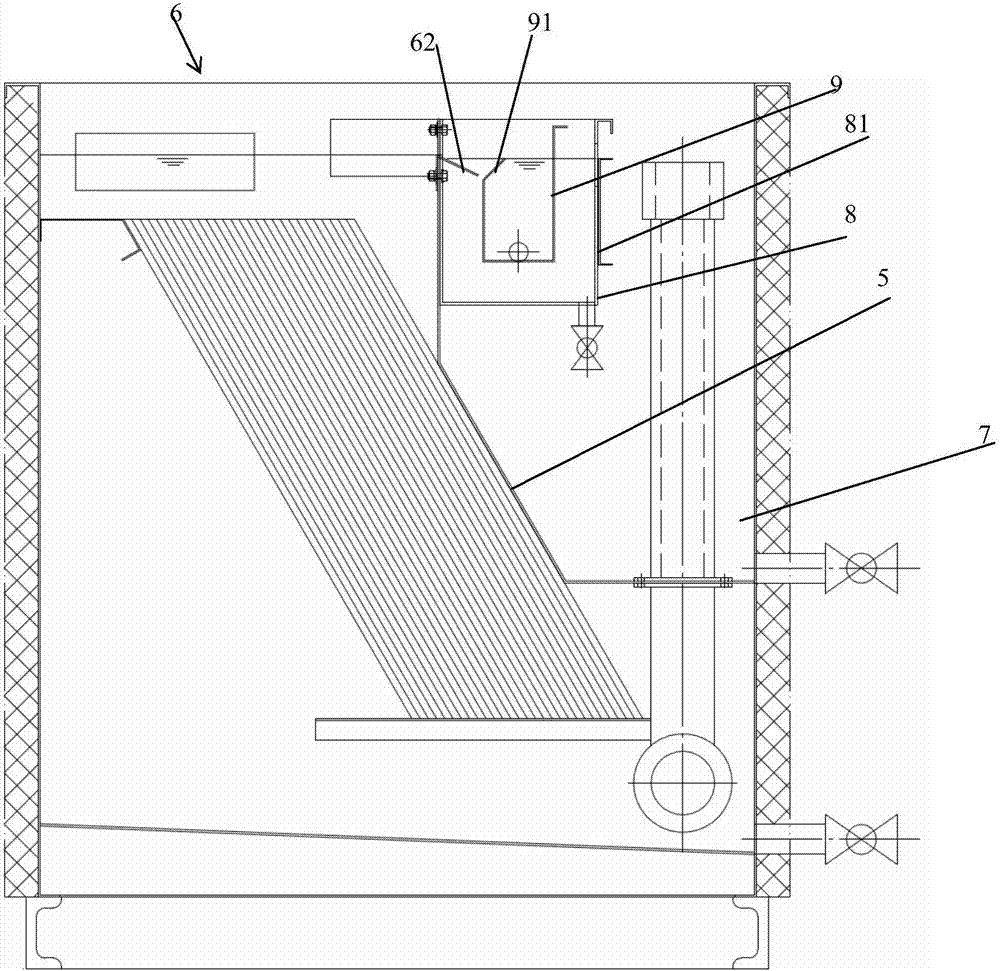
[0019] The liquid skimmed by the oil skimmer enters the oil-water separation device, wherein the installation position of the oil-water separation device is divided into two types, one is to overflow the liquid collected by the oil skimmer into the oil-water separation device, and the treated liquid The water part is pumped back to the degreasing tank, and the other is to pump the liquid overflow collected by the oil skimmer directly to the upper oil-water separation device, and the treated liquid water part returns to the degreasing tank through the pipeline overflow.

[0020] The present invention takes pumping into the oil-water separation device as an example for demonstration, as...


PUM


Abstract

The invention discloses a collection mechanism for oil in concentrated liquid. The collection mechanism used for receiving and treating the concentrated liquid generated from a previous generation portion comprises a flow guide plate, a water chamber and an oil collection chamber, wherein the flow guide plate extending obliquely downwards is arranged on the outer side of a strip-shaped liquid outlet of the previous treatment portion, the water chamber is arranged fixedly on the outer side of the liquid outlet, and the oil collection chamber is arranged fixedly in the water chamber. A side plate on the adjacent side of the oil collection chamber and the liquid outlet is kept at a set distance from the previous treatment portion, the upper end of the top of the side plate extends obliquely upwards along the direction away from the liquid outlet to form a bend section, and the upper side edge of the bend portion is lower than the upper side edge of the flow guide plate. The collection mechanism is integrated, demulsification, packing, a sloping plate and a water cavity for final oil collection and gathering of water filtered and treated at all stages are integrated, a cabinet-type structure is formed, the space is utilized reasonably, the best cooperation ratio of the packing and the sloping plate is realized, step-by-step effective cooperation is achieved, and overall oil removal efficiency is improved.

Description

technical field [0001] The invention relates to the technical field of automobile painting, in particular to an oil collection mechanism and an oil-water separation device in a concentrated liquid. Background technique [0002] The pre-treatment of automobile painting is an important process line, and degreasing is the primary key process. In order to obtain good coating quality and meet the requirements of coating corrosion resistance and appearance decoration, it is necessary to separate oil and water from the degreasing liquid. The ultrafiltration membrane degreasing device has gradually been paid more and more attention to because of the relatively thorough degreasing, but there will be the following disadvantages when using the traditional degreasing liquid ultrafiltration membrane degreasing device: the ultrafiltration degreasing belongs to the method of circulating concentration, which increases the waste liquid. The concentration ratio is generally 30-40 times, and t...

Claims


Application Information

Patent Timeline
Patent Type & Authority Patents(China)
IPC IPC(8): C02F9/10
CPCC02F1/02C02F1/40C02F9/00
Inventor 王海军
Owner AUTOMOTIVE ENG CORP
Learn More