Hydraulic control valve assembly

A technology for hydraulic control valves and components, applied in the directions of lift valves, valve details, valve devices, etc., can solve problems such as failure to eliminate water hammer in pipelines, slow valve opening, and failure to protect the safety of pipeline systems.

Active Publication Date: 2016-07-20
正洲泵阀制造有限公司
View PDF5 Cites 4 Cited by
  • Summary
  • Abstract
  • Description
  • Claims
  • Application Information

AI Technical Summary

Problems solved by technology

At present, the hydraulic control valves used in the market cannot realize the slow opening of the valve, and when the valve is closed, the valve cannot be clo

Method used


Image

  • Hydraulic control valve assembly
  • Hydraulic control valve assembly
  • Hydraulic control valve assembly

Examples


Embodiment Construction

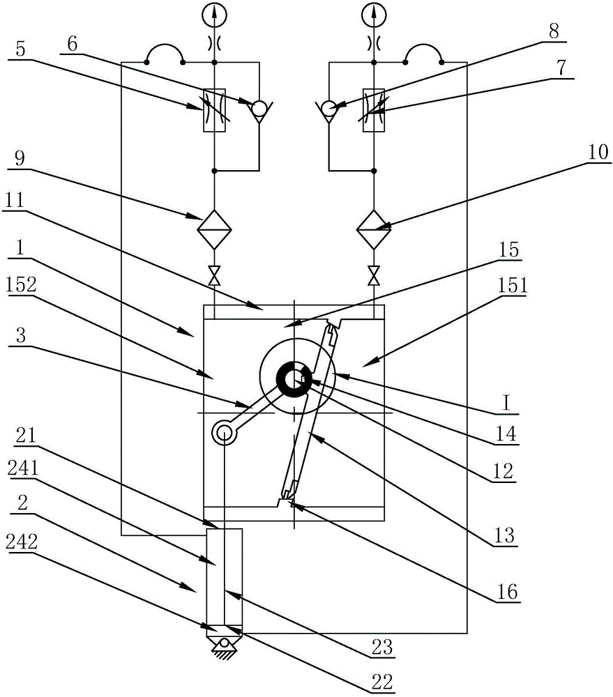
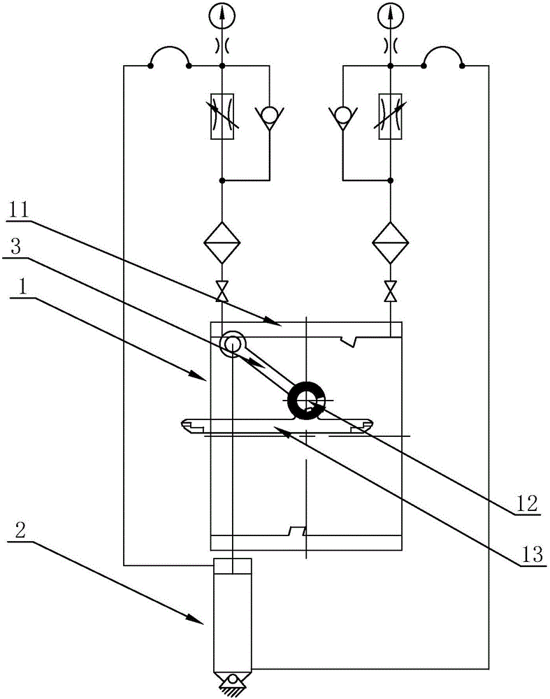
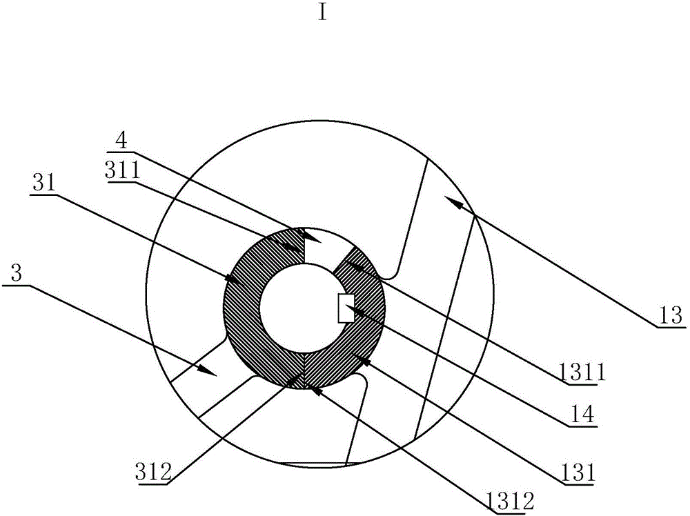
[0019] Such as figure 1 , 2 , 3, a hydraulic control valve assembly includes a control valve 1, a hydraulic cylinder 2, and a connecting rod 3, wherein the control valve 1 includes a valve body 11, a valve stem 12, a valve plate 13, and the valve stem 12 and the valve The body 11 rotates and fits, the valve plate 13 is sleeved on the valve stem 12, the valve plate 13 is connected with the valve stem 12 through the positioning key 14, the valve body 11 is provided with a medium flow channel 15, and one end of the medium flow channel 15 is an inlet port 151, The other end is the outlet end 152, and the valve plate 13 is located between the inlet end 151 and the outlet end 152. The said medium flow path 15 is provided with an annular sealing platform 16, and the valve plate 13 forms a seal with the inner surface of the annular sealing platform 16. The hydraulic cylinder 2 includes a cylinder body 21, the cylinder body 21 is provided with an inner cavity, and the inner cavity is ...


PUM


Abstract

The invention relates to a hydraulic control valve assembly. The hydraulic control valve assembly comprises a control valve, a hydraulic cylinder and a connecting rod, wherein the control valve comprises a valve body, a valve rod and a valve plate, a medium flow channel is formed in the valve body, one end of the medium flow channel is an inlet end, the other end is an outlet end, and the valve plate is located between the inlet end and the outlet end; the hydraulic cylinder comprises a cylinder body, an inner cavity is formed in the cylinder body, a piston is arranged in the inner cavity and divides the inner cavity into a first cavity body and a second cavity body, the piston is provided with a piston rod extending into the first cavity body, the connecting rod is hinged with the piston rod, the first cavity body communicates with the outlet end, the second cavity body communicates with the inlet end, a connecting position of the valve plate and the valve rod is located above the center of the valve plate, and a drive structure is arranged between the connecting rod and the valve plate. With adoption of the technical scheme, the hydraulic control valve assembly can realize slow opening of the valve and can realize first rapid closing and then slow closing of the valve, so that a pipeline water hammer can be eliminated, and the safety of a pipeline system can be protected.

Description

technical field [0001] The invention relates to a hydraulic control valve assembly. Background technique [0002] The hydraulic control valve is installed at the outlet of the water pump, cooperates with the opening and closing of the water pump, and uses the pressure of the medium in the pipeline to control the opening and closing of the valve. At present, the hydraulic control valves used in the market cannot realize the slow opening of the valve, and when the valve is closed, the valve cannot be closed quickly and then slowly closed. Therefore, the water hammer in the pipeline cannot be eliminated, and the pipeline cannot be well protected system security. Contents of the invention [0003] Purpose of the present invention: In order to overcome the defects of the prior art, the present invention provides a hydraulic control valve assembly, which can not only realize the slow opening of the valve, but also realize the rapid closing and then slow closing of the valve, th...

Claims


Application Information

Patent Timeline
IPC IPC(8): F16K1/20F16K31/122F16K47/02
CPCF16K1/20F16K31/122F16K47/023
Inventor 王焕彩黄政洲王骁
Owner 正洲泵阀制造有限公司
Why Eureka
Try Eureka