Solar revolving scenic lantern
A solar energy and revolving lantern technology, applied in lighting and heating equipment, lighting devices, with built-in power supply, etc., can solve the problems of reduced power generation efficiency and excessive consumption, and achieve the effect of enhanced decorative effect
- Summary
- Abstract
- Description
- Claims
- Application Information
AI Technical Summary
Problems solved by technology
Method used
Image

Examples
Embodiment 1
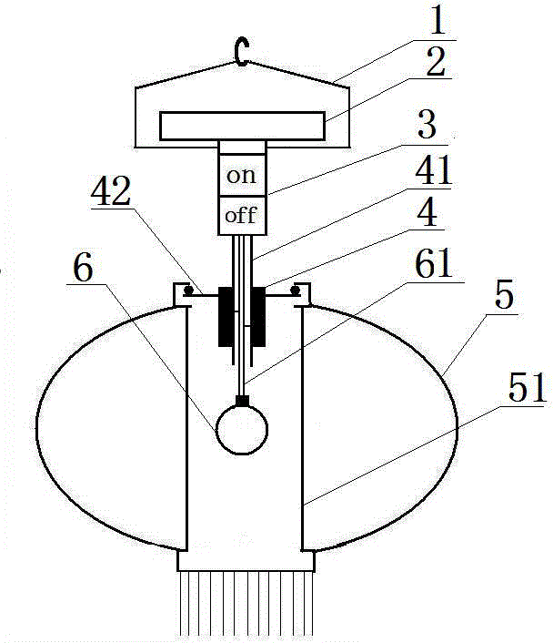
[0013] Example 1, such as figure 1 , a solar revolving lantern, consisting of a solar charging board 2, a rechargeable battery, a controller, a hollow shaft DC gear motor 4, a light bulb 6 and a lantern body 5, the rechargeable battery and the controller (not shown) are located in the working box 3 Inside, the working box 3 is located on the back of the solar charging board 2, and the hook 1 is fixed on the side, and the hook 1 is fixed at the required hanging position. The wire 61 in the hollow shaft 41 supplies power to the bulb 6, and the hollow shaft direct current The deceleration motor 4 supports the opening of the lantern through the telescopic rod 42 fixed to itself, and the rotation of the motor 4 drives the rotation of the lantern body 5 supported by the lantern support rod 51, thereby realizing from solar power generation to power storage through the controller, and then to The rotation of the lantern and the night lighting effect are integrated.
Embodiment 2
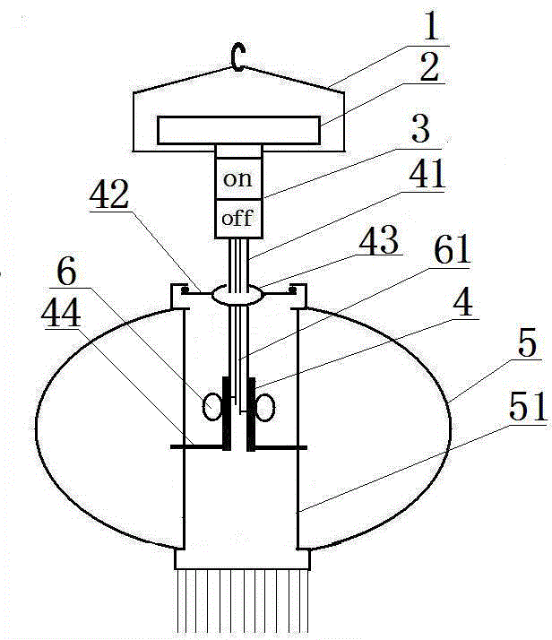
[0014] Example 2, such as figure 2 , as in Example 1, the difference is that: the telescopic rod 42 is fixed on the bearing 43 to support the opening of the lantern; the bearing 43 is fixed on the hollow shaft 41; On the motor 4, the hollow shaft DC geared motor 4 is located in the lantern body 4, and drives the lantern support rod 51 to rotate through the drive rod 44 fixed to itself.
Embodiment 3
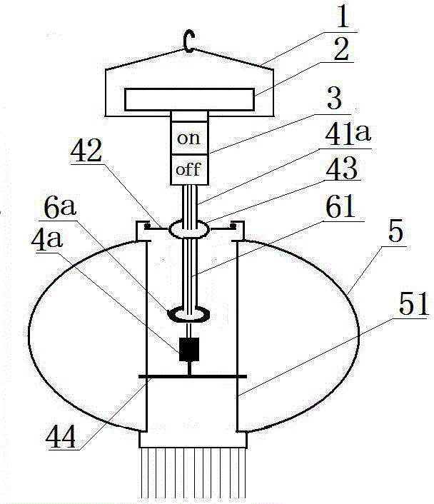
[0015] Example 3, such as image 3 , as in Embodiments 1 and 2, the difference is: the hollow shaft 41 is changed to a hollow tube 41a, the bulb 6 is changed to a ring bulb 64a, the wire 61 is located in the hollow tube 41a, and the bottom is electrically connected to the solid shaft DC geared motor 4a , the motor shaft fixes the drive rod 44 to drive the lantern support rod 51 to rotate, the telescopic rod 42 is fixed on the bearing 43 to support the opening of the lantern, and the bearing 43 is fixed on the hollow tube 41a.
[0016] The electric connection of solar charging board, rechargeable battery, controller, motor and light bulb is omitted for known technology.
PUM
 Abstract
Description
Claims
Application Information
 - Generate Ideas
- Intellectual Property
- Life Sciences
- Materials
- Tech Scout
- Unparalleled Data Quality
- Higher Quality Content
- 60% Fewer Hallucinations
Browse by: Latest US Patents, China's latest patents, Technical Efficacy Thesaurus, Application Domain, Technology Topic, Popular Technical Reports.
© 2025 PatSnap. All rights reserved.Legal|Privacy policy|Modern Slavery Act Transparency Statement|Sitemap|About US| Contact US: help@patsnap.com