Light emitting device

A technology of a light emitting device and a clamping part, which is applied in the field of lighting, can solve the problems of inflexible and convenient use of the light emitting device, and achieve the effects of easy production and promotion, stable clamping, and safe use

Inactive Publication Date: 2016-07-20
邵国晖
0 Cites 0 Cited by

AI-Extracted Technical Summary

Problems solved by technology

[0003] With the development of society, all kinds of light-emitting devices have poured int...

Method used

[0039] The above light emitting device 10, the lamp holder 100 drives the body 200 to slide, and the lamp holder 100 can be placed in different positions of the slide rail 300 according to the needs during use, so that the use of the light emitting device 10 is more flexible and convenient, and its structure is simple, Easy to operate, easy to produce and popularize. Because the lamp holder 100 clamps the slide rail 300, the second electrode on the slide rail 300 is arranged on its side, and the first electrode on the lamp holder 100 is arranged on the two clamping parts 120, making it safer to use and increasing the luminescence Safety features of device 10.
[0042] The groove 321 accommodates the second electrode, which further prevents the user from accidentally touching the electrode and increases the safety of the light emitting device 10 in use. Because the cross section of the groove 321 is trapezoidal, it is safer to use, and because the opening of the groove 321 is small and the bottom surface is large, the connection between the first electrode and the second electrode is more stable.
[0044] The first bending portion 310 and the second bending portion 320 form an acute angle or a right angle, so that the position of the second electrode disposed on the second bending portion 320 is more concealed and difficult to be touched, further increasing the light emitting device 10 safety of use. Wherein, when the included angle between the first bending portion 310 and the second bending portion 320 is 40°, it not only has better safety performance, but also is easier to produce and process.
[0048] Through the elastic force of the elastic member, the clamping of the lamp holder 100 and the slide rail 300 is more stable, and the elastic member makes the use range of the lamp holder 100 wider, and can clamp slide rails 300 of different specifications. In addition, the elastic member prolongs the life of the lamp holder 100 and makes it less prone to damage during use.
[0051] For the light-emitting device 20, the lamp holder 100 drives the body 200 to slide, and the lamp holder 100 can be placed in different positions of the slide rail 300 according to the needs during use, so that the use of the light-emitting device 20 is more flexible and convenient, and its structure is simple, Easy to operate, easy to produce and popularize. Because the lamp holder 100 clamps the slide rail 300, the second electrode on the slide rail 300 is arranged on its side, and the first electrode on the lamp holder 100 is arranged on the two clamping parts 120, making it safer to use and increasing the luminescence The safety performance of the device 20, and because the connecting part 110 and the slide rail 300 are arranged at intervals, the ventilation between the lamp holder 100 and the slide rail 300 is increased, and the heat dissipation effect is increased, thereby increasing the stability of the light emitting device 20, and extending to a certain extent its service life.
[0056] The heat dissipation hole is connected with the groove body formed by the slide rail 300, so that the ventilation effect thereof is better, and the heat dissipation speed of the light emitting device 20 is accelerated, and the heat dissipation effect thereof is increased.
[0058] The connecting portion 110 and the installation portion 210 of the main body 200 are arranged at intervals, which further increases the ventilation effect of the light emitting device 20, thereby increasing its heat dissipation effect. The second heat dissipation hole makes the installation part 210 dissipate heat better.
[0062] In this embodiment, the slide rail 300 includes a first bending portion 310 and a second bending portion 320 disposed at both ends of the first bending portion 310. The second bending portions 320 are located on the same side of the first bending portion 310 , and the first bending portion 310 and the second bending portion 320 enclose a groove. The lamp holder 100 is disposed on the surface of the first bending portion 310 away from the second bending portion 320 . Moreover, both the first bending portion 310 and the second bending portion 320 are hollow and communicate with each other to form the accommodating cavity 301 . Each bending portion is provided with a cooling portion 400 to increase its cooling effect. Wherein, the cooling unit 400 is cooling liquid. In other embodiments, the cooling unit 400 may also be a cooling solid or the like.
[0067] A circulation loop is formed in the slide rail 300, so that the coolant circulates better in the slide rail 300, thereby speeding up the cooling rate of the heated coolant, so that it can better cool the body 200, and then make the light emitting device 30 The cooling effect is better.
[0068] It should be pointed out that, in order to ensure the reliability of the slide rail 300, for example, the inner wall of the circulation loop is provided with a sealing layer to avoid leakage of the coolant. For another example, one of the inner walls of the circulation loop is provided with a miniature refrigerator for auxiliary cooling of the coolant, thus further increasing the heat dissipation effect of the light emitting device 30 .
[0071] For the light-emitting device 40, the lamp holder 100 drives the body 200 to slide, and the lamp holder 100 can be placed in different positions of the slide rail 300 according to the needs during use, so that the use of the light-emitting device 40 is more flexible and convenient, and its structure is simple, Easy to operate, easy to produce and popularize. Because the lamp holder 100 clamps the slide rail 300, the second electrode on the slide rail 300 is arranged on its side, and the first electrode on the lamp holder 100 is arranged on the two clamping parts 120, making it safer to use and increasing the luminescence Safety features of device 40. In addition, the elastic portion is rotatably connected to the connecting portion 110 , so that the lamp holder 100 can be adapted to slide rails 300 of different sizes, increasing the applicable range of the lighting device 40 .
[0073] The pressing part 130 is convenient for adjusting the clamping part 120, so that the lamp holder 100 is more conveniently installed on the slide rail 300. Moreover, the pressing part 130 is detachably disposed on the clamping part 120 , which saves the installation space of the light emitting device 40 , and makes the installed light emitting device 40 not only simple in structure, but also difficult to catch other items.
[...

Abstract

The invention relates to a light emitting device. The light emitting device comprises a lamp holder, a body arranged on the lamp holder and a sliding rail. The lamp holder comprises a connecting part and two clamping parts which are rotatably connected to the two ends of the connecting part correspondingly, and the two clamping parts are located on the same side of the connecting part. First electrodes are arranged on the lamp holder. The body is arranged on the connecting part, and the body and the clamping parts are located on the two sides of the connecting part correspondingly. The body is electrically connected with the first electrodes. The two opposite side faces of the sliding rail are both provided with second electrodes matched with the first electrodes. The extension direction of the second electrodes is identical with the extension direction of the sliding rail. The sliding rail is sleeved with the lamp holder. The two opposite side faces of the sliding rail are clamped by the two clamping parts, and the first electrodes abut against the second electrodes. The light emitting device is more flexible, convenient and faster to use, simple in structure, convenient to operate and easy to produce and popularize.

Application Domain

Lighting support devices

Technology Topic

EngineeringElectrode +1

Image

  • Light emitting device
  • Light emitting device
  • Light emitting device

Examples

  • Experimental program(1)

Example Embodiment

[0033] In order to facilitate the understanding of the present invention, the present invention will be described more fully below with reference to the relevant drawings. The preferred embodiments of the present invention are shown in the drawings. However, the present invention can be implemented in many different forms and is not limited to the embodiments described herein. On the contrary, the purpose of providing these embodiments is to make the disclosure of the present invention more thorough and comprehensive.
[0034] It should be noted that when an element is referred to as being "disposed on" another element, it may be directly on the other element or a central element may also exist. When an element is considered to be "connected" to another element, it can be directly connected to the other element or an intermediate element may be present at the same time. The terms "vertical", "horizontal", "left", "right" and similar expressions used herein are for illustrative purposes only, and do not mean the only implementation.
[0035] Unless otherwise defined, all technical and scientific terms used herein have the same meaning as commonly understood by those skilled in the technical field of the present invention. The terminology used in the specification of the present invention herein is only for the purpose of describing specific embodiments, and is not intended to limit the present invention. The term "and/or" as used herein includes any and all combinations of one or more related listed items.
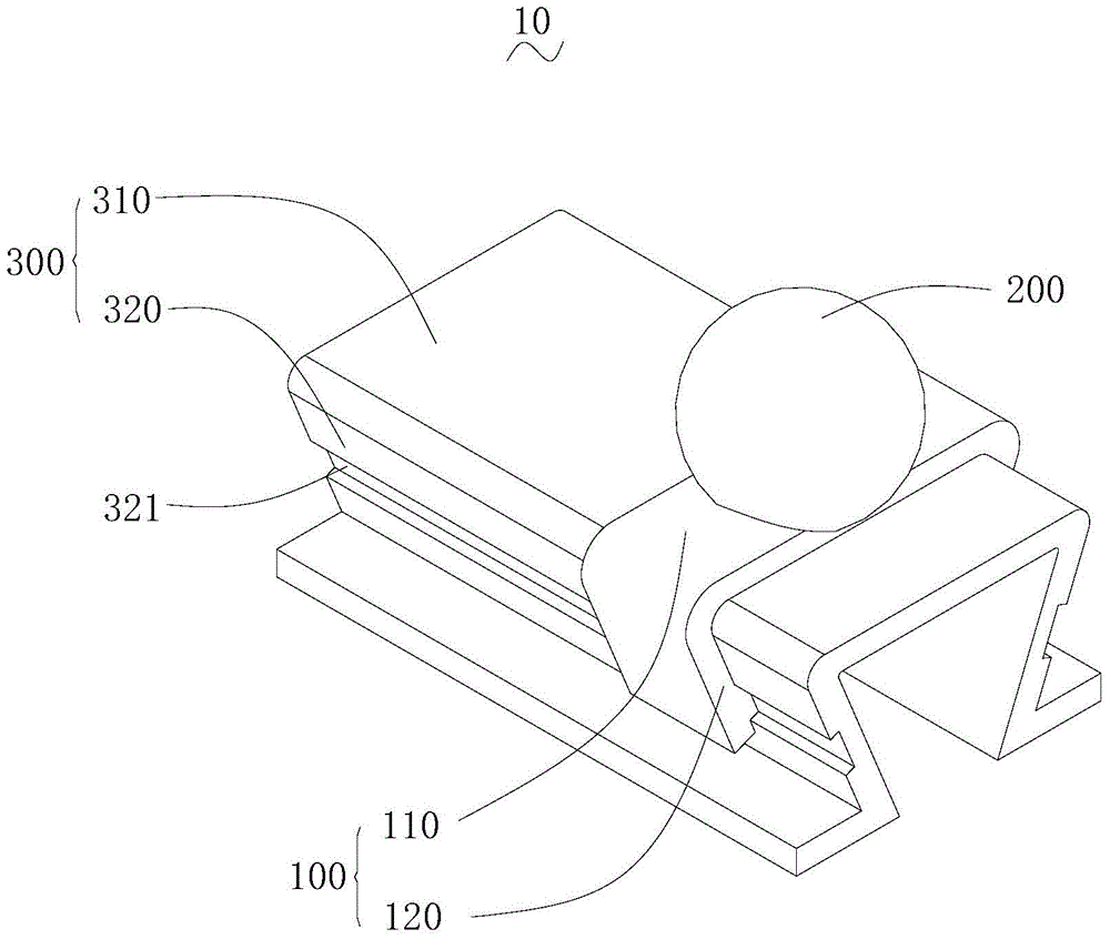
[0036] Such as figure 1 As shown, it is a schematic structural diagram of a light emitting device 10 according to a preferred embodiment of the present invention.
[0037] The light-emitting device 10 includes a lamp holder 100, a body 200 disposed on the lamp holder 100 and a sliding rail 300. The lamp holder 100 includes a connecting portion 110 and two clamping portions 120 respectively disposed at both ends of the connecting portion 110, and the two clamping portions 120 are both located on the same side of the connecting portion 110, and the two clamping portions 120 are on opposite surfaces Both are provided with a first electrode (not shown). The main body 200 is disposed on the connecting portion 110, and is located on both sides of the connecting portion 110 with the clamping portion 120, and the main body 200 is electrically connected to the first electrode. Two opposite sides of the sliding rail 300 are provided with second electrodes (not shown in the figure) matching the first electrodes, and the extending direction of the second electrodes is the same as the extending direction of the sliding rail 300. The lamp holder 100 is sleeved with a sliding rail 300, the two clamping parts 120 clamp two opposite sides of the sliding rail 300, and the first electrode and the second electrode abut against each other.
[0038] When using the above-mentioned light emitting device 10, the slide rail 300 is arranged on the surface to be installed as required and arranged in the required shape, and then the lamp holder 100 is sleeved on the slide rail 300. When in use, the lamp holder 100 is slid on the slide rail 300 and placed in a desired position.
[0039] In the above-mentioned light emitting device 10, the lamp holder 100 drives the main body 200 to slide, and the lamp holder 100 can be placed in different positions of the slide rail 300 according to the needs during use, so that the use of the light emitting device 10 is more flexible and convenient, and its structure is simple and easy to operate. It is easy to produce and promote. Since the lamp holder 100 clamps the sliding rail 300, the second electrode on the sliding rail 300 is arranged on its side surface, and the first electrode on the lamp socket 100 is arranged on the two clamping parts 120, making it safer to use and increasing light emission The safety performance of the device 10.
[0040] In this embodiment, the slide rail 300 includes a first bending portion 310 and a second bending portion 320 disposed at both ends of the first bending portion 310, and the second bending portions 320 are all located on the same side of the first bending portion 310 , And the second electrode is disposed on the second bending portion 320. It can also be understood that the cross-section of the sliding rail 300 is "П"-shaped.
[0041] In order to further increase the safety of the light emitting device 10, for example, grooves 321 are formed on the opposite surfaces of the two second bending parts 320, the extending direction of the grooves 321 is the same as the extending direction of the sliding rail 300, and the second electrode is arranged On the bottom surface of the groove 321. For another example, the cross section of the groove 321 is trapezoidal, and the distance between the opposite side walls of the groove 321 gradually decreases from the bottom of the groove 321 to the opening direction. It can also be understood that the groove 321 is an inverted trapezoid shape.
[0042] The groove 321 accommodates the second electrode, which further prevents the user from touching the electrode due to negligence, and increases the safety of the light emitting device 10 in use. Since the cross section of the groove 321 is trapezoidal, it is safer to use, and because the groove 321 has a small opening and a large bottom surface, the connection between the first electrode and the second electrode is more stable.
[0043] For another example, the first bending portion 310 and the second bending portion 320 form an acute or right angle, that is, the second bending portion 320 is inclined toward the first bending portion 310. Specifically, the included angle between the first bending portion 310 and the second bending portion 320 is 40°. For another example, the included angle between the first bending portion 310 and the second bending portion 320 is between 30° and 90°.
[0044] The first bending portion 310 and the second bending portion 320 are at an acute or right angle, so that the position of the second electrode disposed on the second bending portion 320 is more concealed and not easily touched, which further increases the safety of the light emitting device 10 Sex. Wherein, when the included angle between the first bending portion 310 and the second bending portion 320 is 40°, it is not only safer, but also easier to produce and process.
[0045] According to the actual situation, the sliding rail 300 is provided with a clamping groove, and the extending direction of the clamping groove is the same as the extending direction of the sliding rail 300. A clamping portion is provided on the lamp holder 100, and the clamping portion is slidably clamped in the clamping groove. It should be pointed out that the clamping groove can be provided on the first bending portion 310, the second bending portion 320, or in the groove 321, and the clamping portion can be provided accordingly.
[0046] The clamping groove and the clamping part make the lamp holder 100 and the sliding rail 300 more compact and stable, and are not easy to fall off, thereby increasing the stability of the light emitting device 10.
[0047] In order to further increase the connection and density of the lamp holder 100 and the sliding rail 300, for example, the two clamping portions 120 and the connecting portion 110 are connected by elastic members. Among them, the elastic member is a torsion spring. For another example, the two clamping parts 120 both extend with pressing parts, the two pressing parts and the main body 200 are located on the same side of the connecting part 110, and the two pressing parts are arranged oppositely.
[0048] The elastic force of the elastic member makes the clamping of the lamp holder 100 and the sliding rail 300 more stable, and the elastic member makes the lamp holder 100 more widely used, and can clamp the sliding rail 300 of different specifications. In addition, the elastic member prolongs the life of the lamp holder 100, so that it is not easily damaged during use.
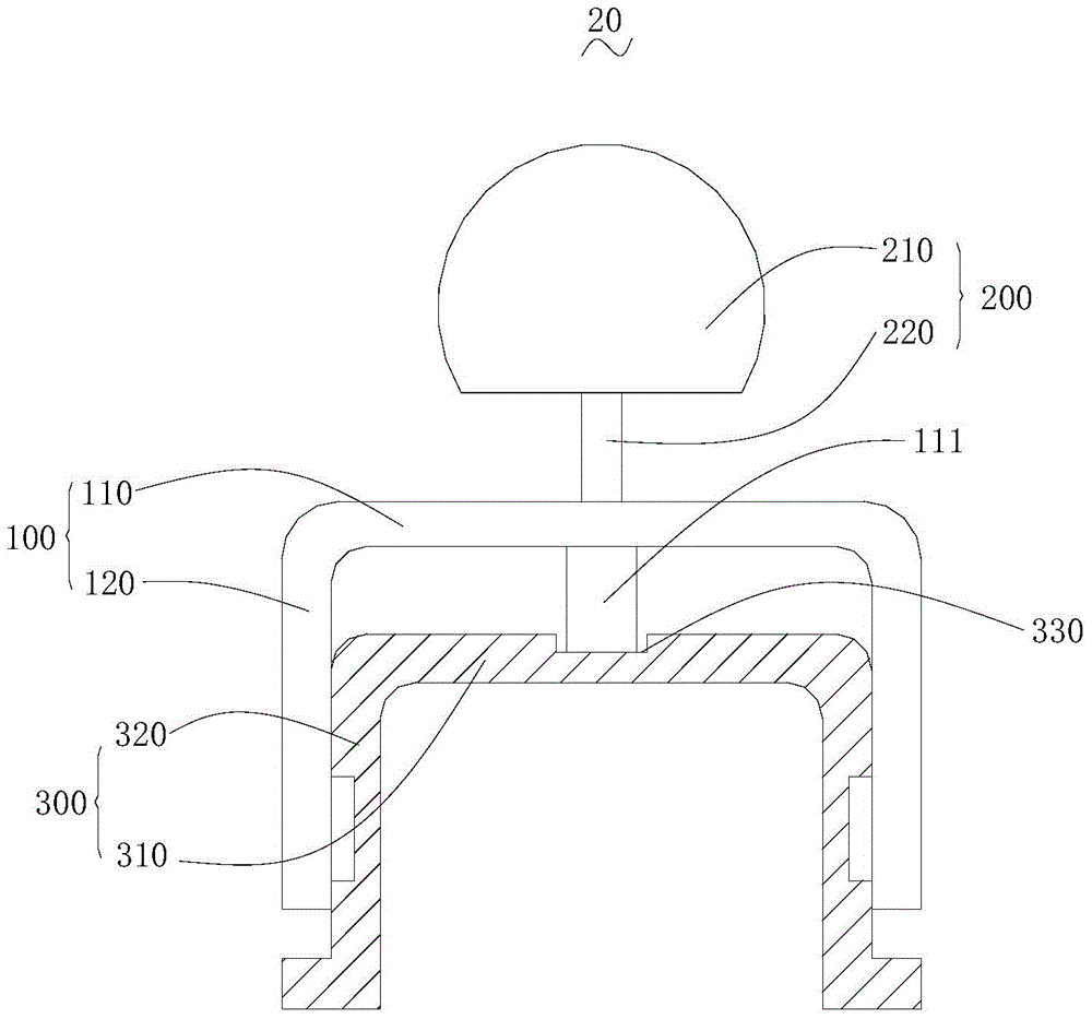
[0049] Please refer to figure 2 , Which is a cross-sectional view of a light emitting device 20 according to another embodiment of the invention.
[0050] The light-emitting device 20 includes a lamp holder 100, a body 200 disposed on the lamp holder 100 and a sliding rail 300. The lamp holder 100 includes a connecting portion 110 and a clamping portion 120 disposed on the connecting portion 110. The clamping portion 120 is provided with a first electrode, and the clamping portion 120 forms an angle toward the connecting portion 110. The main body 200 is disposed on the connecting portion 110, and is located on both sides of the connecting portion 110 with the clamping portion 120, and the main body 200 is electrically connected to the first electrode. The sliding rail 300 is provided with a second electrode matching the first electrode, and the extension direction of the second electrode is the same as the extension direction of the sliding rail 300. The clamping portion 120 is disposed on the sliding rail 300, the first electrode is electrically connected to the second electrode, and the connecting portion 110 is spaced apart from the sliding rail 300.
[0051] In the light emitting device 20, the lamp holder 100 drives the main body 200 to slide, and the lamp holder 100 can be placed in different positions of the slide rail 300 according to the needs during use, which makes the use of the light emitting device 20 more flexible and convenient, and its structure is simple and easy to operate. It is easy to produce and promote. Since the lamp holder 100 clamps the sliding rail 300, the second electrode on the sliding rail 300 is arranged on its side surface, and the first electrode on the lamp socket 100 is arranged on the two clamping parts 120, making it safer to use and increasing light emission The safety performance of the device 20, and because the connecting portion 110 and the sliding rail 300 are spaced apart, the lamp holder 100 and the sliding rail 300 are ventilated, which increases the heat dissipation effect, thereby increasing the stability of the light emitting device 20 and extending it to a certain extent. Its service life.
[0052] According to actual conditions, the sliding rail 300 is an insulating sliding rail 300. The connecting part 110 is perpendicular to the clamping part 120. There are two clamping portions 120, the two clamping portions 120 are both located on the same side of the connecting portion 110, and the two clamping portions 120 are respectively disposed at two ends of the connecting portion 110.
[0053] In this embodiment, the surface of the connecting portion 110 facing the sliding rail 300 is provided with a supporting member 111, and the sliding rail 300 is provided with a supporting groove 330 matching the supporting member 111, and the extending direction of the supporting groove 330 is the same as the extending direction of the sliding rail 300 , The support 111 is accommodated in the slide rail 300 and can slide along the slide rail 300. In this embodiment, the supporting groove 330 is disposed on the first bending portion 310. In other embodiments, the supporting groove 330 may also be provided on the second bending portion 320, or on the first bending portion 310 and the second bending portion 320 at the same time.
[0054] The support 111 enables the lamp holder 100 to be more stably arranged on the sliding rail 300, and can ensure that the connecting portion 110 and the sliding rail 300 are spaced apart, and the distance from the sliding rail 300 will not be reduced due to long-term use.
[0055] In order to further increase the heat dissipation effect, according to actual conditions, for example, the slide rail 300 includes a first bending portion 310 and a second bending portion 320 disposed at both ends of the first bending portion 310. The second bending portions 320 are all located on the same side of the first bending portion 310, and the first bending portion 310 and the second bending portion 320 enclose a trough. It can also be understood that the cross section of the slide rail 300 is " П" type. A first heat dissipation hole is provided on the first bending portion 310, and the first heat dissipation hole communicates with the groove body.
[0056] The heat dissipation holes are connected to the trough formed by the sliding rail 300, so that the ventilation effect is better, and the heat dissipation speed of the light emitting device 20 is accelerated, and the heat dissipation effect thereof is increased.
[0057] For another example, the main body 200 includes a mounting portion 210 and a connecting rod 220 disposed on the mounting portion 210. The connecting rod 220 is disposed on the connecting portion 110, and the mounting portion 210 and the connecting portion 110 are spaced apart. The mounting portion 210 is provided with a bulb, and the bulb is electrically connected to the first electrode, and the mounting portion 210 is provided with a second heat dissipation hole.
[0058] The connecting portion 110 and the mounting portion 210 of the main body 200 are spaced apart, which further increases the ventilation effect of the light-emitting device 20, thereby increasing its heat dissipation effect. The second heat dissipation hole makes the mounting part 210 better dissipate heat.
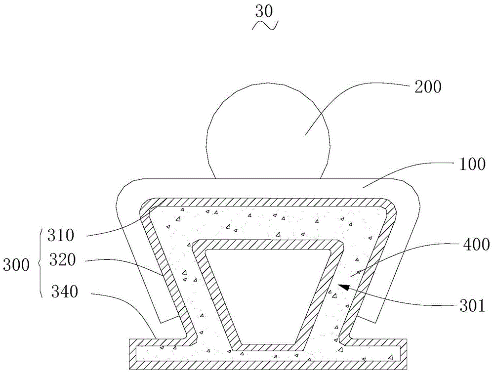
[0059] Please refer to image 3 , Which is a cross-sectional view of a light emitting device 30 according to another embodiment of the present invention.
[0060] The light emitting device 30 includes: a lamp holder 100, a body 200 disposed on the lamp holder 100, a sliding rail 300, and a cooling part 400. The lamp holder 100 is provided with a first electrode part, and the lamp holder 100 is located between the main body 200 and the sliding rail 300. The sliding rail 300 is provided with a second electrode matching the first electrode, the extension direction of the second electrode is the same as the extension direction of the sliding rail 300, and the first electrode is electrically connected to the second electrode. The sliding rail 300 has a hollow structure and has an accommodating cavity 301, and the extending direction of the accommodating cavity 301 is the same as the extending direction of the sliding rail 300. The cooling part 400 is accommodated in the accommodation cavity 301 and fills the accommodation cavity 301.
[0061] In the light-emitting device 30, the lamp holder 100 drives the main body 200 to slide, and the lamp holder 100 can be placed in different positions of the slide rail 300 according to the needs during use, which makes the use of the light-emitting device 30 more flexible and convenient, and has a simple structure and convenient operation. It is easy to produce and promote. The cooling part 400 improves the heat dissipation effect of the sliding rail 300, thereby increasing the stability and life of the light emitting device 30.
[0062] In this embodiment, the sliding rail 300 includes a first bending portion 310 and a second bending portion 320 provided at both ends of the first bending portion 310. The second bending portions 320 are all located on the same side of the first bending portion 310, and the first bending portion 310 and the second bending portion 320 surround a groove body. The lamp holder 100 is disposed on the surface of the first bending portion 310 away from the second bending portion 320. In addition, the first bending portion 310 and the second bending portion 320 are both hollow structures and communicate with each other to form an accommodating cavity 301. Each bending part is provided with a cooling part 400 to increase its cooling effect. Among them, the cooling part 400 is a cooling liquid. In other embodiments, the cooling part 400 may also be a cooling solid or the like.
[0063] According to actual conditions, the sliding rail 300 may also be a hollow rectangular body, a cylinder, a prism, etc., and the cooling part 400 is located in the hollow accommodating cavity 301 of the sliding rail 300 at this time.
[0064] In order to speed up cooling, for example, a fan is provided on the inner wall of the tank to assist the air flow in the tank. Wherein, the fan is arranged on the bottom surface of the tank and located at one end of the sliding rail 300.
[0065] The fan can assist the air flow in the trough, accelerate the cooling of the cooling part 400 in the slide rail 300, and thereby increase the heat dissipation effect of the main body 200. When the fan is arranged at the end of the sliding rail 300, the air flow in the trough is more smooth.
[0066] According to the actual situation, the slide rail 300 also includes a circulation portion 340 connecting the two second bending portions 320. The circulation portion 340 is a hollow structure and communicates with the first bending portion 310 and the second bending portion 320, and forms Circulation loop. It can also be understood that the sliding rail 300 is a hollow prism body, and each side wall of the prism has a hollow structure and communicates with each other.
[0067] A circulation loop is formed in the slide rail 300, so that the cooling liquid can better circulate in the slide rail 300, thereby accelerating the cooling rate of the heated cooling liquid, so that it can better cool the body 200, thereby making the cooling effect of the light emitting device 30 better. good.
[0068] It should be pointed out that, in order to ensure the reliability of the slide rail 300, for example, the inner wall of the circulation loop is provided with a sealing layer to avoid leakage of the coolant. For another example, a micro-refrigerator is provided on one of the inner walls of the circulation loop to assist in cooling the coolant, so as to further increase the heat dissipation effect of the light emitting device 30.
[0069] Please refer to Figure 4 , Which is an exploded view of a light emitting device 40 according to another embodiment of the present invention.
[0070] The light-emitting device 40 includes a lamp holder 100, a body 200 disposed on the lamp holder 100 and a sliding rail 300. The lamp holder 100 includes a connecting portion 110, and two clamping portions 120 respectively rotatably connecting the two ends of the connecting portion 110, and the two clamping portions 120 are both located on the same side of the connecting portion 110, and the lamp holder 100 is provided with a first electrode. The main body 200 is disposed on the connecting portion 110, and is located on both sides of the connecting portion 110 with the clamping portion 120, and the main body 200 is electrically connected to the first electrode. Two opposite sides of the sliding rail 300 are provided with second electrodes matching the first electrode, and the extending direction of the second electrode is the same as the extending direction of the sliding rail 300. The lamp holder 100 is sleeved with a sliding rail 300, the two clamping parts 120 clamp two opposite sides of the sliding rail 300, and the first electrode and the second electrode abut against each other.
[0071] In the light-emitting device 40, the lamp holder 100 drives the main body 200 to slide, and the lamp holder 100 can be placed in different positions of the slide rail 300 according to the needs during use, which makes the use of the light-emitting device 40 more flexible and convenient, and has a simple structure and convenient operation. It is easy to produce and promote. Since the lamp holder 100 clamps the sliding rail 300, the second electrode on the sliding rail 300 is arranged on its side surface, and the first electrode on the lamp socket 100 is arranged on the two clamping parts 120, making it safer to use and increasing light emission Safety performance of device 40. In addition, the elastic part rotates to connect to the connecting part 110, so that the lamp holder 100 can be applied to slide rails 300 of different sizes, and the application range of the light emitting device 40 is increased.
[0072] In order to facilitate the installation of the light emitting device 40, for example, the two clamping parts 120 both extend with a pressing part 130, the two pressing parts 130 and the main body 200 are located on the same side of the connecting part 110, and the two pressing parts 130 are disposed oppositely. According to actual conditions, for example, the pressing portion 130 is detachably provided on the clamping portion 120. Specifically, the pressing portion 130 is screwed to the clamping portion 120. For another example, the pressing portion 130 is spliced ​​and arranged on the clamping portion 120.
[0073] The pressing portion 130 facilitates adjustment of the clamping portion 120, so that the lamp holder 100 is more conveniently installed on the sliding rail 300. In addition, the pressing portion 130 is detachably disposed on the clamping portion 120, which saves the installation space of the light-emitting device 40, so that the light-emitting device 40 after installation is not only simple in structure, but also difficult to hook and scratch other objects.
[0074] In order to save the space occupied by the light-emitting device 40, for example, a pressing groove matching the pressing portion 130 is provided on the clamping portion 120, and the pressing portion 130 is slidably disposed on the clamping portion 120 and received in the pressing groove. According to the actual situation, the pressing part 130 is provided with a holding part for taking out the clamping part 120 in the pressing groove. The supporting part is located on the side of the pressing part 130 away from the bottom surface of the pressing groove.
[0075] When in use, the pressing part 130 is slid out of the pressing groove by the supporting part, and the pressing part 130 is pressed to set the lamp holder 100 on the sliding rail 300. In this way, not only the space occupied by the light emitting device 40 is saved, the structure is more concise, and the operation is convenient.
[0076] According to actual conditions, the lamp holder 100 further includes a number of expansion parts, which are detachably disposed on the pressing part 130. For example, the expansion part and the pressing part 130 are spliced ​​and arranged.
[0077] The expansion part reduces the force of the user pressing the clamping part 120, making it more convenient and labor-saving to use, and the expansion part is detachably disposed on the pressing part 130, saving space in use.
[0078] It should be pointed out that, in order to increase the stability of the clamping between the lamp holder 100 and the sliding rail 300, for example, the lamp holder 100 further includes an elastic member 140. Two ends of the elastic member 140 are respectively disposed at the end of the connecting portion 110 and the end. Connected to the clamping portion 120. It can also be understood that the lamp holder 100 includes two elastic members 140, and the two elastic members 140 are respectively disposed at two ends of the connecting portion 110 and correspondingly connected to the clamping portion 120 corresponding to the end. In this embodiment, the elastic member 140 is a torsion spring.
[0079] The elastic force of the elastic member 140 makes the clamping between the lamp holder 100 and the sliding rail 300 more stable. In addition, the elastic member 140 also prolongs the life of the lamp holder 100, so that it is not easily damaged during use.
[0080] According to actual conditions, the connecting portion 110 and the clamping portion 120 are provided with elastic grooves matching the elastic member 140, and the elastic member 140 is accommodated in the elastic groove. It can also be understood that the elastic groove at one end of the clamping portion 120 communicates with the elastic groove on the corresponding clamping portion 120, and the elastic member 140 is accommodated in two communicating elastic grooves.
[0081] The elastic groove facilitates the installation of the clamping portion 120 so that it does not affect the connection between the clamping portion 120 and the sliding rail 300.
[0082] Please refer to Figure 5 , Which is a cross-sectional view of a light emitting device 50 according to another embodiment of the present invention.
[0083] The light-emitting device 50 includes a lamp holder 100, a main body 200 disposed on the lamp holder 100 and a sliding rail 300. The lamp holder 100 includes a connecting portion 110 and two clamping portions 120 respectively disposed at both ends of the connecting portion 110, and the two clamping portions 120 are both located on the same side of the connecting portion 110, and the two clamping portions 120 are on opposite surfaces Both are provided with a first electrode. The body 200 is disposed on the connecting portion 110, and is located on both sides of the connecting portion 110 with the clamping portion 120, and the body 200 is electrically connected to the first electrode. Two opposite sides of the sliding rail 300 are provided with a groove 321, a second electrode arranged in the groove 321, and a plurality of protective covers 500 rotatably arranged in the opening area of ​​the groove 321. The second electrode matches the first electrode, and the extension direction of the second electrode is the same as the extension direction of the sliding rail 300. The adjacent protective covers 500 abut and cover the groove 321. Each clamping portion 120 abuts at least one protective cover 500 so that the protective cover 500 rotates and the second electrode leaks out. The protective cover 500 is spaced apart from the second electrode. The lamp holder 100 is sleeved with a sliding rail 300, the two clamping portions 120 clamp two opposite sides of the sliding rail 300, and the first electrode and the second electrode abut against each other.
[0084] When the light-emitting device 50 is used, the protective cover 500 covers the groove 321. When the lamp holder 100 is installed on the slide rail 300, the clamping portion 120 abuts against at least one protective cover 500 and exposes a part of the second cover covered by the protective cover 500. The electrode makes the first electrode on the clamping portion 120 abut the second battery.
[0085] In the light-emitting device 50, the lamp holder 100 drives the main body 200 to slide, and the lamp holder 100 can be placed in different positions of the slide rail 300 according to the needs during use, which makes the use of the light-emitting device 50 more flexible and convenient, and has a simple structure and convenient operation. It is easy to produce and promote. Since the lamp holder 100 clamps the sliding rail 300, the second electrode on the sliding rail 300 is arranged on its side surface, and the first electrode on the lamp socket 100 is arranged on the two clamping parts 120, making it safer to use and increasing light emission The safety performance of the device 50. The protective cover 500 further increases the use safety of the light emitting device 50.
[0086] In this embodiment, a plurality of protective covers 500 are rotatably arranged on the sliding rail 300 on the side close to the main body 200, and are arranged at intervals from the second electrode. That is, the same side of each protective cover 500 is arranged on the connecting portion 110, and for another example, the side of each protective cover 500 away from the main body 200 is rotatably arranged on the sliding rail 300.
[0087] According to actual conditions, the sliding rail 300 has a resetting part, one end of the resetting part is arranged on the sliding rail 300 and the other end is arranged on the protective cover 500 for resetting the protective cover 500. In this embodiment, the reset part is a torsion spring. Specifically, the slide rail 300 includes a first bending portion 310 and a second bending portion 320 disposed at both ends of the first bending portion 310, and the second bending portions 320 are all located on the same side of the first bending portion 310. The groove 321 and the protective cover 500 are both disposed on the second bending part 320.
[0088] The reset part enables the protective cover 500 to be reset after the lamp holder 100 is separated, so that the protective cover 500 can better cover the second electrode, thereby increasing the safety of the light emitting device 50.
[0089] In this embodiment, the protective cover 500 is inclined toward the bottom surface of the groove 321. Specifically, the included angle between the protective cover 500 and the side wall of the groove 321 is 45°-80°. Preferably, the included angle between the protective cover 500 and the side wall of the groove 321 is 60°.
[0090] The protective cover 500 is inclined toward the bottom surface of the groove 321, so that the protective cover 500 can better protect the second electrode.
[0091] For another example, the protective cover 500 has a plate-like structure, and its width is 0.5 cm to 1.5 cm. Preferably, the width of the protective cover 500 is 0.7 cm. It can also be understood that the plurality of protective covers 500 are arranged along the extending direction of the sliding rail 300.
[0092] When the width of the protective cover 500 is 0.7 cm, the protective effect of the protective cover 500 on the second electrode is ensured, and the size of the protective cover 500 is large enough to facilitate mass production and installation.
[0093] Please refer to Image 6 , Which is a schematic structural diagram of a light emitting device 60 according to another embodiment of the present invention.
[0094] The light emitting device 60 includes a lamp holder 100, a body 200 disposed on the lamp holder 100 and a sliding rail 300. The lamp holder 100 includes a connecting portion 110 and a clamping portion 120 disposed on the connecting portion 110. The clamping portion 120 is provided with a first electrode, and the clamping portion 120 forms an angle toward the connecting portion 110. The main body 200 includes a rotating part 230 and a lamp body 240 rotatably disposed on the rotating part 230. The rotating portion 230 is disposed on the connecting portion 110, and is located on both sides of the connecting portion 110 with the clamping portion 120, and the body 200 is electrically connected to the first electrode. The sliding rail 300 is provided with a second electrode matching the first electrode, and the extension direction of the second electrode is the same as the extension direction of the sliding rail 300. The clamping portion 120 is disposed on the sliding rail 300, the first electrode is electrically connected to the second electrode, and the connecting portion 110 and the sliding rail 300 are spaced apart.
[0095] In the above-mentioned light emitting device 60, the lamp holder 100 drives the main body 200 to slide, and the lamp holder 100 can be placed in different positions of the sliding rail 300 according to the needs during use, so that the use of the light emitting device 60 is more flexible and convenient, and its structure is simple and easy to operate. It is easy to produce and promote. Since the lamp holder 100 clamps the sliding rail 300, the second electrode on the sliding rail 300 is arranged on its side surface, and the first electrode on the lamp socket 100 is arranged on the two clamping parts 120, making it safer to use and increasing light emission Safety performance of device 60. The lamp body 240 is rotatably arranged on the rotating part 230, so that the adjustment range of the light emitting device 60 is wider, and the illumination direction can be adjusted according to actual needs.
[0096] In this embodiment, the rotating part 230 includes a rotating main body 231 and two rotating support members 232 arranged at intervals on the rotating main body 231. The two rotating support members 232 are respectively located on opposite sides of an end of the rotating main body 231, and the lamp body 240 rotates. The lamp body 240 is arranged on the rotating support 232 and the lamp body 240 is located between the two rotating supports 232. Wherein, the lamp body 240 can rotate 360° relative to the rotating support 232.
[0097] The rotating part 230 has a simple structure and is convenient for production and installation. Since the distance from one end of the rotating support 232 to the opposite end of the lamp body 240 is less than the length of the rotating support 232, the lamp body 240 has a wide adjustment range and a wide range of applications.
[0098] In order to facilitate the installation of the lamp body 240, for example, the rotating part 230 is connected with the lamp body 240 through a rotating shaft, and the rotating shaft passes through one of the rotating support members, the lamp body 240 and the other rotating support member 232 in sequence. For another example, convex parts are provided on opposite sides of the lamp body 240, and concave parts matching the convex parts are provided on the opposite sides of the rotating support, and the convex parts are rotated and accommodated in the concave parts.
[0099] In order to further increase the adjustment direction of the lamp body, for example, the rotating part includes a rotating main body and a rotating support provided on the rotating main body, and there is one rotating support. The rotating support member is rotatably arranged on the rotating main body through the rotating member, and the rotating axis of the rotating member is perpendicular to the rotating axis of the lamp body. It can also be understood that the rotating member is disposed between the rotating support member and the rotating body.
[0100] The rotating member expands the adjustment range of the lamp body 240, and further increases the adjustment range of the light emitting device 60, so that the lamp body 240 can be adjusted to any angle as required.
[0101] According to the actual situation, at least two installation positions are provided on the connecting part, and the main body is arranged on the installation positions. Among them, the number of bodies corresponds to the number of mounting positions, and each mounting position is provided with a body. Specifically, the main body is screwed to the connecting part.
[0102] A suitable number of main bodies 200 can be selected and installed in multiple installation positions according to actual needs, which further increases the adjustment range of the light emitting device 60. The main body 200 is screwed to the connecting portion 110, which makes the connection simple, convenient for installation and disassembly, and thus convenient for maintenance.
[0103] Please refer to Figure 7 , Which is a structural diagram of a dressing table 70 to which the light-emitting device 10 of the present invention is applied.
[0104] The dressing table 70 includes a main body portion 710, a mirror frame 720 disposed on the main body portion 710, a mirror 730 disposed on the mirror frame 720, and a light emitting device 10 disposed on the mirror frame 720. The light emitting device 10 includes a lamp holder, a body arranged on the lamp holder, and a sliding rail arranged on the mirror frame 720. The lamp holder includes a connecting portion and two clamping portions respectively arranged at both ends of the connecting portion, and the two clamping portions are located on the same side of the connecting portion, and the two clamping portions are provided with first electrodes on the opposite surfaces. The main body is arranged on the connecting part, and the clamping part is respectively located on both sides of the connecting part, and the main body is electrically connected with the first electrode. Two opposite sides of the sliding rail are provided with second electrodes matching the first electrode, and the extending direction of the second electrode is the same as the extending direction of the sliding rail. The lamp holder is sleeved with sliding rails, two clamping parts clamp two opposite sides of the sliding rails, and the first electrode and the second electrode abut against each other.
[0105] In the dressing table 70, the lamp holder drives the main body to slide, and the lamp holder can be placed in different positions of the slide rail according to the needs during use, which makes the use of the light emitting device 10 more flexible and convenient, and its structure is simple, convenient to operate, and easy to produce and promote . In addition, the light-emitting device 10 is slidably disposed on the dressing table 70, and the user can select the position of the light-emitting device 10 according to needs, and then adjust the illumination angle of the light-emitting device 10, so that the dressing table 70 has a wider application range. Since the lamp holder clamps the sliding rail, the second electrode on the sliding rail is arranged on its side, and the first electrode on the lamp holder is arranged on the two clamping parts, which makes it safer to use and increases the safety performance of the light emitting device 10 .
[0106] According to the actual situation, at least part of the side surface of the mirror frame 720 is provided with sliding rails, and the sliding rail is located on the side surface of the mirror frame 720 where the mirror 730 is arranged. For example, there are multiple sliding rails, and the multiple sliding rails are arranged at intervals on the peripheral side of the mirror frame 720 where the mirror 730 is provided. Wherein, at least one lamp holder is provided on each slide rail. Or part of the slide rail is provided with a lamp holder. It should be pointed out that the sides of the mirror frame 720 where the mirror 730 are provided are all provided with sliding rails. At this time, there are two lamp holders. According to actual needs, there can be more than one lamp holder.
[0107] The multiple sliding rails are arranged at intervals to ensure the adjustability of the light emitting device 10, while reducing materials and saving costs. At least one lamp holder is provided on each sliding rail, which further increases the adjustability of the light emitting device 10 on the dressing table 70, and the local brightness can be adjusted as required.
[0108] In this embodiment, the side surface of the mirror frame 720 provided with the mirror 730 is provided with an installation groove, and the slide rail is accommodated in the installation groove. Among them, the slide rail is clamped in the installation slot. Specifically, a hook is provided on the side of the slide rail facing the installation slot, a card slot is provided on the installation slot, and the hook is clamped in the card slot. It can also be understood that the clamping portion is accommodated in the installation groove, and the second electrode provided on the clamping portion is accommodated in the installation groove.
[0109] The installation groove facilitates the installation of the slide rail, and further ensures the safety of the light emitting device 10 in use. The hook and the slot have a simple structure, are convenient for installation and production, and are convenient for popularization of the dressing table 70.
[0110] Please refer to Figure 8 , Which is a schematic diagram of the structure of a table 80 to which the light-emitting device 10 of the present invention is applied.
[0111] The table 80 includes: a table top 810 and a light emitting device 10 arranged on the table top 810. The light emitting device 10 includes a lamp holder, a main body arranged on the lamp holder, and a sliding rail arranged on a table top 810. The lamp holder includes a connecting portion and two clamping portions respectively arranged at both ends of the connecting portion, and the two clamping portions are located on the same side of the connecting portion, and the two clamping portions are provided with first electrodes on the opposite surfaces. The main body is arranged on the connecting part, and the clamping part is respectively located on both sides of the connecting part, and the main body is electrically connected with the first electrode. Two opposite sides of the sliding rail are provided with second electrodes matching the first electrode, and the extension direction of the second electrode is the same as the extension direction of the sliding rail. The lamp holder is sleeved with sliding rails, the two clamping parts clamp two opposite sides of the sliding rails, and the first electrode and the second electrode abut against each other.
[0112] In the table 80, the lamp holder drives the main body to slide, and the lamp holder can be placed in different positions of the slide rail according to the needs during use, which makes the use of the light emitting device 10 more flexible and convenient, and has a simple structure and convenient operation, which is convenient for production and promotion. In addition, the light emitting device 10 is slidably arranged on the table 80, and the user can select the position of the light emitting device 10 according to needs, so that the table 80 has a wider application range. Since the lamp holder clamps the sliding rail, the second electrode on the sliding rail is arranged on its side, and the first electrode on the lamp holder is arranged on the two clamping parts, which makes it safer to use and increases the safety performance of the light emitting device 10 .
[0113] In order to make the table 80 easy to use, for example, the table top 810 has a sliding groove 811, and the sliding rail is accommodated in the sliding groove 811. Wherein, the sliding rail is arranged on the periphery of the surface of the table top 810. At this time, the sliding grooves 811 are arranged on the surface of the table top 810 and are distributed along the periphery of the table top 810, and the sliding rail is not higher than the bottom surface of the sliding groove 811 relative to the bottom surface of the table top 810. s surface.
[0114] The sliding rail is accommodated in the sliding groove 811, so that the table top 810 is more tidy, does not affect the placement of objects on the table top 810, and does not reduce the area of ​​the table top 810 for placing objects.
[0115] In this embodiment, the cross section of the slide rail is circular, the lamp holder is rotatably arranged on the slide rail, and its rotation axis is the same as the extension direction of the slide rail. It can also be understood that the lamp holder can slide around the slide rail. The periphery of the table top 810 is provided with an opening 812 communicating with the sliding groove 811. The extending direction of the opening 812 is perpendicular to the extending direction of the sliding groove 811. The lamp holder is accommodated in the opening 812 and is flush with the surface of the table top 810. It should be noted that the body is telescopically arranged on the lamp holder. It should be noted that, for another example, a notch is provided on the periphery of the table top 810 to make the top of the table 810 a stepped shape, the slide rail is arranged on the bottom surface of the notch, and the bottom surface of the slide rail relative to the notch is not higher than the table top 810.
[0116] When using the above table 80, slide the lamp holder to the required position as needed, and adjust the height of the main body by telescoping. After use, rotate the lamp holder to accommodate it in the opening 812 and be flush with the surface of the table top 810, and retract the body.
[0117] The lamp holder is rotatably arranged on the slide rail, which not only can adjust the light emitting angle of the lamp body, but also facilitates the storage of the light emitting device 10. When lighting is not required, the light emitting device 10 can be rotated and stored flat without occupying the placement space of the desktop 810. In this way, not only the desktop 810 is more tidy, but also the placement space of the desktop 810 is not affected.
[0118] In order to further facilitate storage, for example, the table 80 further includes a receiving box, which is arranged on the side of the table 80 and communicates with the opening 812 for receiving the main body. It can also be understood that the lamp holder is accommodated in the opening 812 and is flush with the desktop 810, and the body is accommodated in the accommodating box.
[0119] The accommodating box accommodates the main body, so that when the main body is not in use, it can be better stored without touching other objects and causing damage, which further facilitates storage. In addition, the accommodating slot can be dustproof and waterproof, and protect the body, which increases the service life of the light emitting device 10.
[0120] It should be pointed out that the sliding rail can also be arranged on at least part of the peripheral side of the table top 810, and the sliding groove 811 is opened on the side of the table top 810 at this time. For example, the sliding rail is arranged on the peripheral side of the desktop 810, that is, the sliding rail is arranged on all sides of the desktop 810. For another example, the sliding rail is only arranged on one side of the desktop 810.
[0121] The technical features of the above-mentioned embodiments can be combined arbitrarily. In order to make the description concise, all possible combinations of the various technical features in the above-mentioned embodiments are not described. However, as long as there is no contradiction in the combination of these technical features, All should be considered as the scope of this specification.
[0122] The above-mentioned embodiments only express several embodiments of the present invention, and the descriptions are more specific and detailed, but they should not be understood as limiting the scope of the invention patent. It should be pointed out that for those of ordinary skill in the art, without departing from the concept of the present invention, several modifications and improvements can be made, and these all fall within the protection scope of the present invention. Therefore, the protection scope of the patent of the present invention should be subject to the appended claims.

PUM

no PUM

Description & Claims & Application Information

We can also present the details of the Description, Claims and Application information to help users get a comprehensive understanding of the technical details of the patent, such as background art, summary of invention, brief description of drawings, description of embodiments, and other original content. On the other hand, users can also determine the specific scope of protection of the technology through the list of claims; as well as understand the changes in the life cycle of the technology with the presentation of the patent timeline. Login to view more.

Similar technology patents

Photoelectric sensor for position of sun

InactiveCN101650173AEffective tracking range expandedSimple structure
Owner:WUHAN UNIV OF TECH

Magnetic cooling apparatus and control method thereof

ActiveUS20130180263A1simple structure
Owner:SAMSUNG ELECTRONICS CO LTD

Dual-Drivetrain of Power-Assist Vehicle

InactiveUS20100181130A1enhance uphill momentumsimple structure
Owner:CHOU WEN CHENG

Classification and recommendation of technical efficacy words

  • Simple structure
  • easy to operate

Lancet device

InactiveUS7303573B2inexpensively mass-producedeasy to operate
Owner:ABBOTT DIABETES CARE INC

Rapid and non-invasive optical detection of internal bleeding

InactiveUS20050065436A1easy to operaterapid and accurate result
Owner:HO WINSTON ZONH +2
Why Eureka
Try Eureka