
Device and method for unconventional sub-aperture splicing interference detection of free-form surface

A technology of interference detection and detection method, which is applied in measuring devices, optical devices, instruments, etc., can solve the problem of no longer adapting to free-form surfaces, etc., and achieve the effect of high-precision interference detection

Active Publication Date: 2018-10-26
ZHEJIANG UNIV
View PDF12 Cites 0 Cited by
  • Summary
  • Abstract
  • Description
  • Claims
  • Application Information

AI Technical Summary

Problems solved by technology

Therefore, the spherical wave or aspheric wave emitted by the interferometer can be used for interference detection, but because the wavefront slope returned by the free-form surface is not continuous and uniform, its local slope may exceed the range of the interferometer (interference fringe density is very large), The sub-aperture division measurement must be performed on it, and the surface degree of freedom of the free-form surface determines that the traditional circular or annular sub-aperture division is no longer suitable for the sub-aperture splicing interferometry of the free-form surface

Method used


Image

  • Device and method for unconventional sub-aperture splicing interference detection of free-form surface
  • Device and method for unconventional sub-aperture splicing interference detection of free-form surface
  • Device and method for unconventional sub-aperture splicing interference detection of free-form surface

Examples


Embodiment

[0060] An example of the application of the present invention to splicing interference detection of unconventional sub-apertures on free-form surfaces is described as follows.

[0061] The measured free-form surface is a double conical surface, and its equation is

[0062]

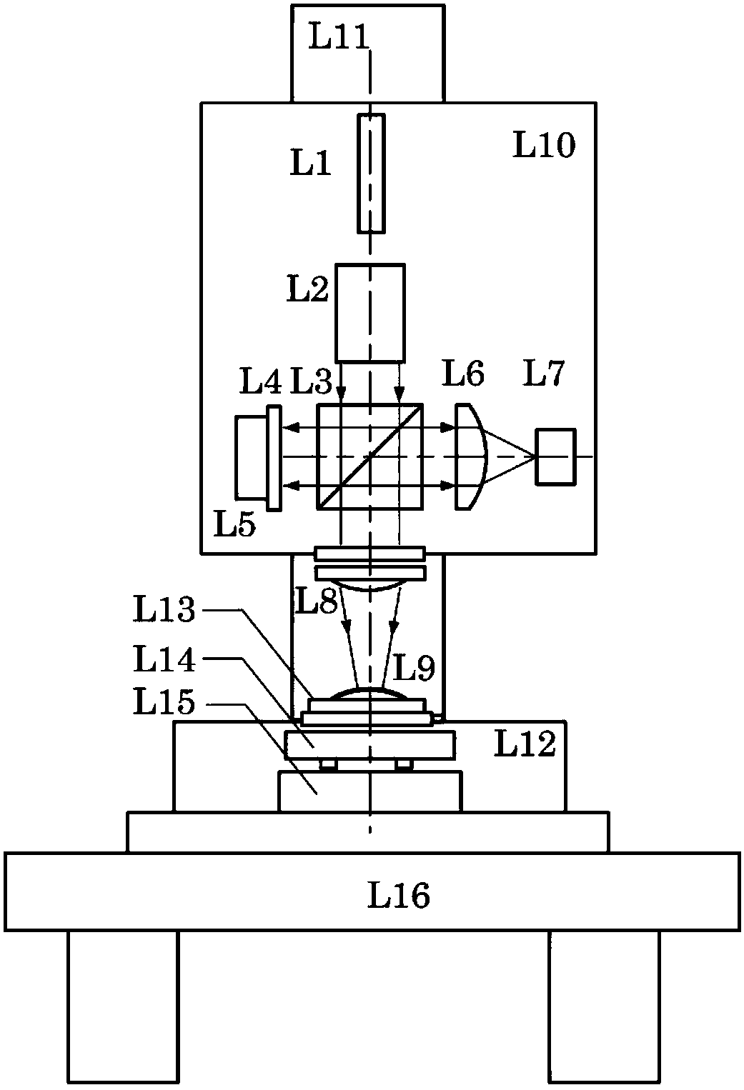
[0063] figure 1 It is the diagram of the free-form surface unconventional sub-aperture splicing interference detection device, the laser wavelength is λ=632.8nm, where r x =239.8mm, r y =240.2mm,k x =-1.2,k y =-0.8. The thin beam emitted by the frequency-stabilized laser L1 is expanded into a wide-beam parallel light by the collimator beam expander system L2, and the parallel light travels forward to the beam splitter L3 and is divided into two beams. One path propagates forward to the reference plane mirror L4 and then returns to the original path as a reference wave; the other path propagates forward to a part of the zero mirror L8 and then returns from the measured free-form surface L9, and pass...


PUM


Abstract

The invention discloses a free-form surface unconventional subaperture splicing interference detection device and method. The main effect of most of the optical free-form surfaces in an optical system is to provide or correct a part of on-axis or off-axis aberration at present. Aspheric wavefront emergent from a non-null interference system is used as reference, and the detection interferogram of the free-form surface is divided into the shape of unconventional subapertures according to the shape features of the detection interferogram. Meanwhile, experimental mechanism parameters are configured according to the subaperture division parameters in a model so that an orthogonal polynomial is derived according to the shape of the subapertures to perform wavefront fitting, and finally a full-aperture shape is spliced through a synchronous reverse optimization reconstruction algorithm. Waste of resolution caused by the conventional circular or annular subapertures can be avoided, the number of the subapertures can be reduced and splicing of the unconventional subapertures of the free-form surface can be realized.

Description

technical field [0001] The invention belongs to the technical field of detection of free-form surfaces, and in particular relates to a device and method for splicing interference detection of unconventional sub-apertures on free-form surfaces. Background technique [0002] Due to its large surface degree of freedom, the optical free-form surface can provide or correct different on-axis or off-axis aberrations in a targeted manner, and at the same time meet the requirements of high performance, light weight and miniaturization of modern optical systems, thus gradually becoming a modern optical system. The new favorite in engineering. Although there has been steady development in design, processing, and testing, the high-precision requirements for the surface shape of optical components in the imaging field have limited the large-scale application of free-form surfaces. In particular, the detection technology of free-form surfaces has become the most important factor restrict...

Claims


Application Information

Patent Timeline
Patent Type & Authority Patents(China)
IPC IPC(8): G01B11/24
CPCG01B11/2441
Inventor 刘东杨甬英张磊师途
Owner ZHEJIANG UNIV
Learn More