
A system and method for intelligently compensating interference detection with large local surface shape errors

A technology of interference detection and surface shape error, which is applied in the direction of measuring devices, instruments, and optical devices, can solve the problems of limited precision, limited modes of deformation mirror difference, low detection resolution or detection accuracy, etc., to improve work Performance, Realize Grinding, Effects for Improving Dynamic Range

Active Publication Date: 2021-11-19
NAT UNIV OF DEFENSE TECH
View PDF8 Cites 0 Cited by
  • Summary
  • Abstract
  • Description
  • Claims
  • Application Information

AI Technical Summary

Problems solved by technology

However, the calibration of the deflection measurement system itself is also very difficult. The accuracy of the entire interferometry system is limited by the accuracy of the deflection measurement system and the number of drivers. poor form
[0007] In summary, in terms of realizing local large error analysis, existing detection methods cannot be realized based on commercial wavefront interferometers, the detection device has complex structure, high cost, and low detection resolution or detection accuracy

Method used


Image

  • A system and method for intelligently compensating interference detection with large local surface shape errors
  • A system and method for intelligently compensating interference detection with large local surface shape errors

Examples


Embodiment Construction

[0036] In order to make the purpose, technical solutions and advantages of the embodiments of the present invention clearer, the spirit of the disclosure of the present invention will be clearly described below with the accompanying drawings and detailed descriptions. Any person skilled in the art will understand the embodiments of the present invention. , when it can be changed and modified by the technology taught in the content of the present invention, it does not depart from the spirit and scope of the content of the present invention. The exemplary embodiments and descriptions of the present invention are used to explain the present invention, but not to limit the present invention.

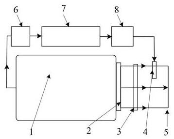
[0037] An intelligent compensation interference detection system for local large surface errors provided in this embodiment includes a wavefront interferometer 1, a standard lens 2, a static compensator 3, an adaptive optical element 4, a surface to be measured 5, and far-field light intensi...


PUM


Abstract

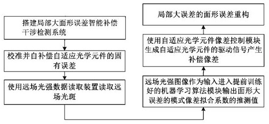
A system and method for intelligent compensation interference detection of local large surface shape errors, including a wavefront interferometer, a standard lens, a static compensator, an adaptive optical element, and a surface to be measured. The wavefront interferometer is equipped with a standard lens; the standard lens and the surface to be measured A static compensator and an adaptive optical element are arranged in sequence, the wavefront interferometer is connected to the far-field light intensity data reading device, and the far-field light intensity data reading device reads the far-field light intensity image obtained by the wavefront interferometer and inputs it to the Controller; the controller predicts and outputs the estimated value of the surface shape large error mode aberration fitting coefficient according to the far-field light intensity image; the adaptive optical element aberration control module fits the surface shape large error mode aberration according to the surface to be measured The estimated value of the coefficient generates the driving signal of the adaptive optical element, drives the adaptive optical element to generate compensation aberration, and realizes the intelligent compensation detection of the large error of the surface shape to be measured. The invention improves the processing efficiency of complex optical surface shapes.

Description

technical field [0001] The invention belongs to the technical field of optical surface shape detection, and in particular relates to an interference detection system and method for intelligent compensation of local large surface shape errors. Background technique [0002] The processing of optical parts generally goes through several stages of milling, grinding, and polishing. The grinding stage is the key to determining whether the entire processing can be efficiently converged to high precision. However, the certainty of grinding is far less than that of polishing, especially the local curvature changes of complex optical surfaces make it difficult for the grinding disc to fit the surface to be processed, and it is prone to large local errors, such as common edge collapse or warping , and local pits or protrusions, the corresponding error gradient is too large, resulting in too dense or even invisible interference fringes, far beyond the Nyquist sampling frequency of the d...

Claims


Application Information

Patent Timeline
Patent Type & Authority Patents(China)
IPC IPC(8): G01B11/25G01B9/02
CPCG01B9/02055G01B11/25
Inventor 薛帅戴一帆石峰宋辞
Owner NAT UNIV OF DEFENSE TECH
Learn More