Measuring head of pneumatic instrument

A technology of measuring head and pneumatic measuring instrument, applied in the field of machinery, can solve problems such as large error and failure to meet the detection standard of pneumatic measuring instrument, and achieve the effect of solving the problem of drilling pressure and simplifying the process of opening holes

Inactive Publication Date: 2016-07-20
SUZHOU GUOLIANG MEASURE TECH CO LTD
View PDF6 Cites 4 Cited by
  • Summary
  • Abstract
  • Description
  • Claims
  • Application Information

AI Technical Summary

Problems solved by technology

However, when the inner diameter of the circular gauge is quite large, due to the increase in the thickness of the steel member, the opening requires extremely high-strength punching and drilling or tapping equipment. Strict symmetry and high smoothness lead to

Method used


Image

  • Measuring head of pneumatic instrument
  • Measuring head of pneumatic instrument
  • Measuring head of pneumatic instrument

Examples


Embodiment Construction

[0018] The present invention will be described in detail below with reference to the accompanying drawings and specific embodiments.

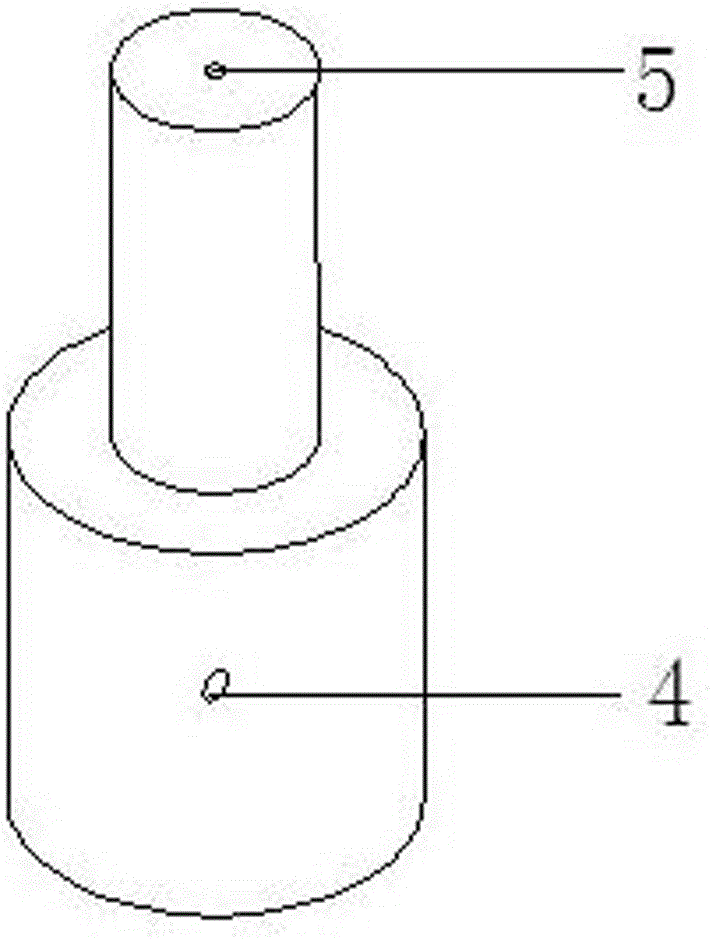
[0019] like figure 1 As shown in the figure, the measuring head of the existing technical pneumatic gauge is an integral inseparable structure, and its vent hole end 5 and vent port 4 must strictly pass through the solid steel member, and must be strictly symmetrical, so when the thickness of the steel member becomes thicker, the machining Accuracy and punch pressure present difficulties.

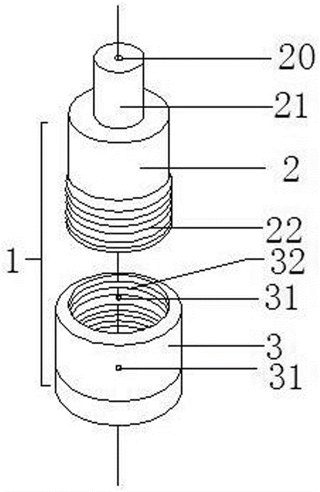
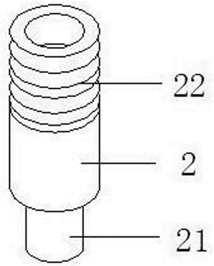
[0020] like figure 2 As shown in -3, a measuring head of a pneumatic measuring instrument of the present invention includes a measuring head body 1, and the measuring head body 1 includes a vent hole end 3 and a vent hole end 2, the vent hole end is slotted, and a pair of symmetrical The ventilation hole 31 is provided with an inner thread 32 in the inner ring of the groove; the ventilation hole end 2 includes an outer thread end 22 and an air inlet end 2...


PUM


Abstract

The invention relates to a measuring head of a pneumatic instrument. The measuring head comprises a measuring head body including an air hole end and a ventilating hole end. Slotting is carried out in the air hole end; a pair of symmetric circular venting holes is formed in the slot; and an internal thread is formed in the groove in an annular hole. The ventilating hole end includes an external thread end and an air inlet port; slotting is carried out in the external thread end; and a through hole is formed in the air inlet port and extends to the external thread end and is communicated with the slot in the external thread end. In the prior art, hole drilling is carried out on a measuring head in an integrated entity mode and three holes are perpendicular to each other to form an inverted T shape; and when the measuring head is thickened and dimension of the measuring head is increased, the processing becomes difficult. Therefore, on the one hand, the opened air hole distance is reduced by separating the measuring head; and on the other hand, the thickness of the hole formed inside the measuring head is reduced. And thus the hole drilling process is simplified; and a problem that hole drilling needs the high drilling pressure can be solved.

Description

technical field [0001] The invention belongs to the field of machinery, in particular to a measuring head of a pneumatic instrument. Background technique [0002] The measurement principle of the pneumatic gauge is a comparative measurement method. The measurement method is to convert the length signal into an air flow signal, and pass the float mark value in the graduated glass tube, which is called a float type pneumatic measuring instrument; or convert the air signal into an electric signal through a gas-electric converter. Indication value, called electronic column pneumatic measuring instrument. Pneumatic measuring instrument is a measuring instrument that can be assembled by multiple units. It can be matched with different pneumatic probes to measure various parameters. Due to its many advantages, pneumatic measuring instruments have been widely used in the machinery manufacturing industry. Its advantages are as follows: [0003] 1. There are many measurement items...

Claims


Application Information

Patent Timeline
IPC IPC(8): G01B13/00
CPCG01B13/00
Inventor 赵永海
Owner SUZHOU GUOLIANG MEASURE TECH CO LTD
Why Eureka
Try Eureka