Pipe Drilling Machine

A technology for drilling machines and pipe fittings, which is used in boring/drilling, drilling/drilling equipment, metal processing machinery parts, etc. Achieve the effect of improving work efficiency, reducing the scribing process, and simplifying the drilling process of pipe fittings

Inactive Publication Date: 2017-10-31
国网山东省电力公司宁津县供电公司 +1
View PDF6 Cites 0 Cited by
  • Summary
  • Abstract
  • Description
  • Claims
  • Application Information

AI Technical Summary

Problems solved by technology

[0002] The pipe wall drilling of pipe parts is generally carried out by marking first and then drilling with a drilling machine. The disadvantage is that the two processes are completed on the marking platform and the drilling machine respectively. During the processing, the workpiece needs to be removed from the marking platform. Transported to the drilling machine, and because the workpiece cannot be automatically indexed, the workpiece rolls many times during the processing, not only the work efficiency is low, but also the processing accuracy is poor

Method used


Image

  • Pipe Drilling Machine
  • Pipe Drilling Machine
  • Pipe Drilling Machine

Examples


Embodiment Construction

[0053] The implementation of the present invention will be illustrated by specific specific examples below, and those skilled in the art can easily understand other advantages and effects of the present invention from the contents disclosed in this specification.

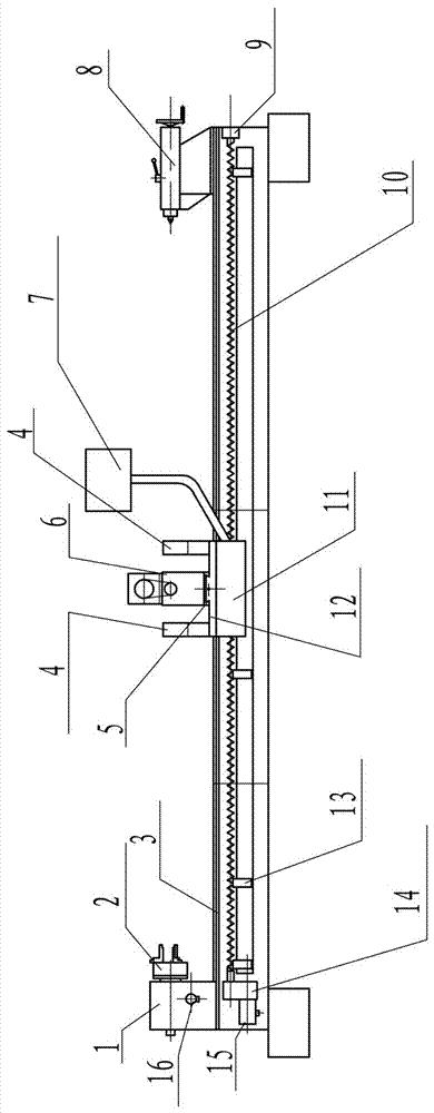
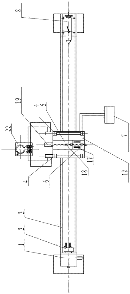
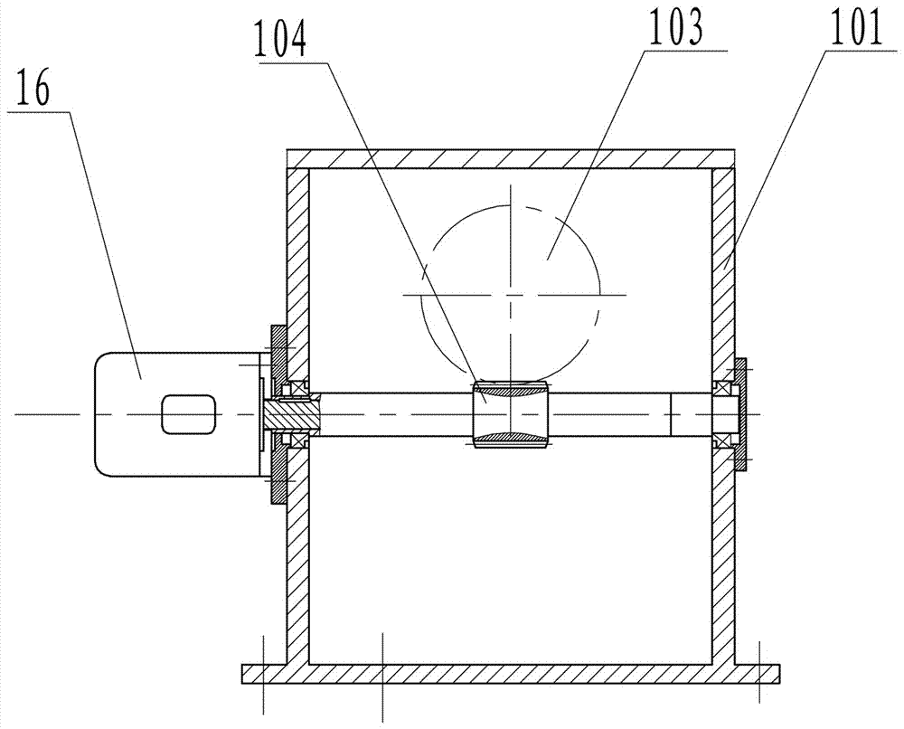
[0054] see Figure 1 to Figure 7 . It should be noted that the structures, proportions, sizes, etc. shown in the drawings of this specification are only used to match the content disclosed in the specification, for those who are familiar with this technology to understand and read, and are not used to limit the conditions for the implementation of the present invention , so it has no technical substantive meaning, and any modification of structure, change of proportional relationship or adjustment of size shall still fall within the scope of the disclosure of the present invention without affecting the functions and objectives of the present invention. within the range covered by the technical content. At the same...


PUM


Abstract

The invention provides a pipe fitting drilling machine comprising a machine body, an indexing spindle box disposed at a front end of the machine body to clamp a workpiece, a longitudinal drive system, a carriage disposed above the machine body and capable of sliding along a carriage moving guide rail with a transverse moving guide rail disposed at an upper portion of the carriage, a slide carriage frame located below the carriage and fixedly connected to the carriage, a longitudinal nut in screwing fit with a longitudinal lead screw to form a longitudinal lead screw pair together, a slide plate disposed above the carriage and capable of sliding along the transverse moving guiding rail, a transverse lead screw fixed to the carriage, a transverse nut fixed to the slide plate and in screwing fit with the transverse lead screw to form a transverse lead screw pair together, a transverse servomotor fixed to the carriage and having an output shaft fixedly connected to the transverse lead screw, a drill rod case fixed to the slide plate and used for drilling a pipe fitting, a tailstock assembly disposed at a rear end of the machine body to press against a workpiece, and a workpiece clamping device disposed above the carriage to clamp a workpiece during drilling.

Description

technical field [0001] The invention relates to a mechanical processing equipment, in particular to a pipe fitting drilling machine. Background technique [0002] The pipe wall drilling of pipe parts is generally carried out by marking first and then drilling with a drilling machine. The disadvantage is that the two processes are completed on the marking platform and the drilling machine respectively. During the processing, the workpiece needs to be removed from the marking platform. Transported to the drilling machine, and because the workpiece cannot be automatically indexed, the workpiece rolls many times during the machining process, which not only has low work efficiency, but also poor machining accuracy. Contents of the invention [0003] In view of the above-mentioned shortcomings of the prior art, the object of the present invention is to provide a pipe drilling machine for solving the above-mentioned problems in the prior art. [0004] In order to achieve the abo...

Claims


Application Information

Patent Timeline
Patent Type & Authority Patents(China)
IPC IPC(8): B23B41/00B23Q16/06B23Q5/40B23Q3/08
CPCB23B41/00B23Q3/064B23Q3/08B23Q5/402B23Q16/065
Inventor 王峰苑立军张金海王立松
Owner 国网山东省电力公司宁津县供电公司
Why Eureka
Try Eureka