
Drip metering method of ultrasonic water meter

A measurement method, ultrasonic technology, applied in the direction of volume measurement, measuring device, measuring capacity, etc., can solve the problems of water company loss, etc., and achieve the effects of long service life, increased range ratio, and wide range ratio

Active Publication Date: 2016-07-20
HARBIN SHENGCHANG TECH DEV
View PDF4 Cites 2 Cited by
  • Summary
  • Abstract
  • Description
  • Claims
  • Application Information

AI Technical Summary

Problems solved by technology

[0004] The purpose of the present invention is to solve the problem that due to the structural disadvantages of the existing ordinary mechanical water meters, the user steals water by means of dripping water, causing losses to the water supply company, and now provides a method for measuring dripping water in ultrasonic water meters

Method used


Image

  • Drip metering method of ultrasonic water meter
  • Drip metering method of ultrasonic water meter

Examples


specific Embodiment approach 1

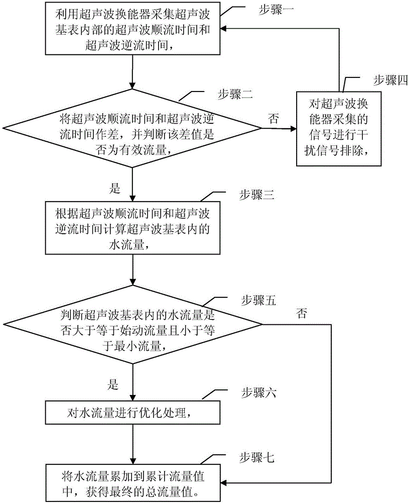
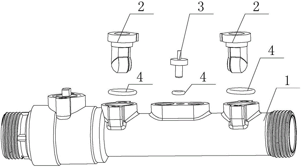
[0020] Specific implementation mode one: refer to figure 1 and figure 2 Specifically explain this embodiment, the ultrasonic water meter drip measurement method described in this embodiment, the method is realized by an ultrasonic water meter, and the water meter includes: an ultrasonic base meter 1 and an ultrasonic transducer 2;

[0021] There are two openings on the side wall of the ultrasonic base meter 1, and the two ultrasonic facing ends of the ultrasonic transducer 2 respectively pass through the two openings and are located inside the ultrasonic base meter 1, and the openings are sealed, and the ultrasonic transducer 2 The two ultrasonic opposing ends face each other,

[0022] The ultrasonic water meter drip metering method comprises the following steps:

[0023] Step 1: Use the ultrasonic transducer 2 to collect the ultrasonic downstream time and ultrasonic countercurrent time inside the ultrasonic base meter 1, and then perform step 2,

[0024] Step 2: Make a di...

specific Embodiment approach 2

[0034] Specific embodiment 2: This embodiment is to further explain the ultrasonic water meter drip measurement method described in specific embodiment 1. In this embodiment, in step 2, it is judged whether the difference between the ultrasonic downstream time and the ultrasonic countercurrent time is the effective flow rate. The specific method is: compare the difference between the ultrasonic forward flow time and the ultrasonic reverse flow time with the value greater than the starting threshold, if the difference is greater than the starting threshold value, it is a valid flow, otherwise it is invalid;

[0035] The above starting threshold value is the difference between the ultrasonic forward flow time and the ultrasonic backward flow time when water is dripping.

specific Embodiment approach 3

[0036] Specific embodiment three: this embodiment is to further illustrate the ultrasonic water meter drip metering method described in specific embodiment one. The method is: filtering the signal collected by the ultrasonic transducer 2 .


PUM


Abstract

The invention provides a drip metering method of an ultrasonic water meter and relates to the field of application of water meter. The drip metering method is used for solving the problem that a running-water company`s loss is generated when a user utilizes a drip method to steal water due to the structural defects of an existing common mechanical water meter. The drip metering method of the ultrasonic water meter comprises the following steps: collecting the water flow by use of an ultrasonic time difference theory; and comparing the collected water flow with starting flow and minimum flow during measurement, thereby eliminating drip errors and further improving the metering accuracy of the water meter. The drip metering method is applicable to any environment requiring the water meter to meter the water flow.

Description

technical field [0001] The invention belongs to the application field of water meters, in particular to an ultrasonic water meter drip metering method. Background technique [0002] At present, there have been many disputes and disadvantages that are difficult to resolve in the project of using mechanical water meters. For example, due to the severe wear and tear of the mechanical water meter for many years, the accuracy of the heat meter is reduced, and eventually it cannot be used, causing the user to pay for maintenance many times, causing disputes that are difficult to resolve between the user and the water company; The method of releasing water and stealing water for a long time escaped the inspection of the water company, which brought certain losses to the water company without basis for investigation. [0003] To sum up, the disadvantages of the existing ordinary mechanical water meters in practical application include: large pressure loss, easy to block, serious we...

Claims


Application Information

Patent Timeline
IPC IPC(8): G01F1/66G01F15/00
CPCG01F1/66G01F15/007Y02A20/00
Inventor 崔崇民
Owner HARBIN SHENGCHANG TECH DEV
Learn More