

Method and system of unmanned plane omnibearing obstacle avoidance based on binocular vision
A technology for binocular vision and unmanned aerial vehicles, applied in the field of unmanned aerial vehicles, can solve problems such as the inability to guarantee real-time performance and the inability to adapt to binocular vision to avoid obstacles and the large amount of computation, and achieve the effect of low power consumption
- Summary
- Abstract
- Description
- Claims
- Application Information
AI Technical Summary
Problems solved by technology
Method used
Image

Examples
Embodiment Construction
[0020] The present invention will be described in detail below in conjunction with the accompanying drawings and embodiments.
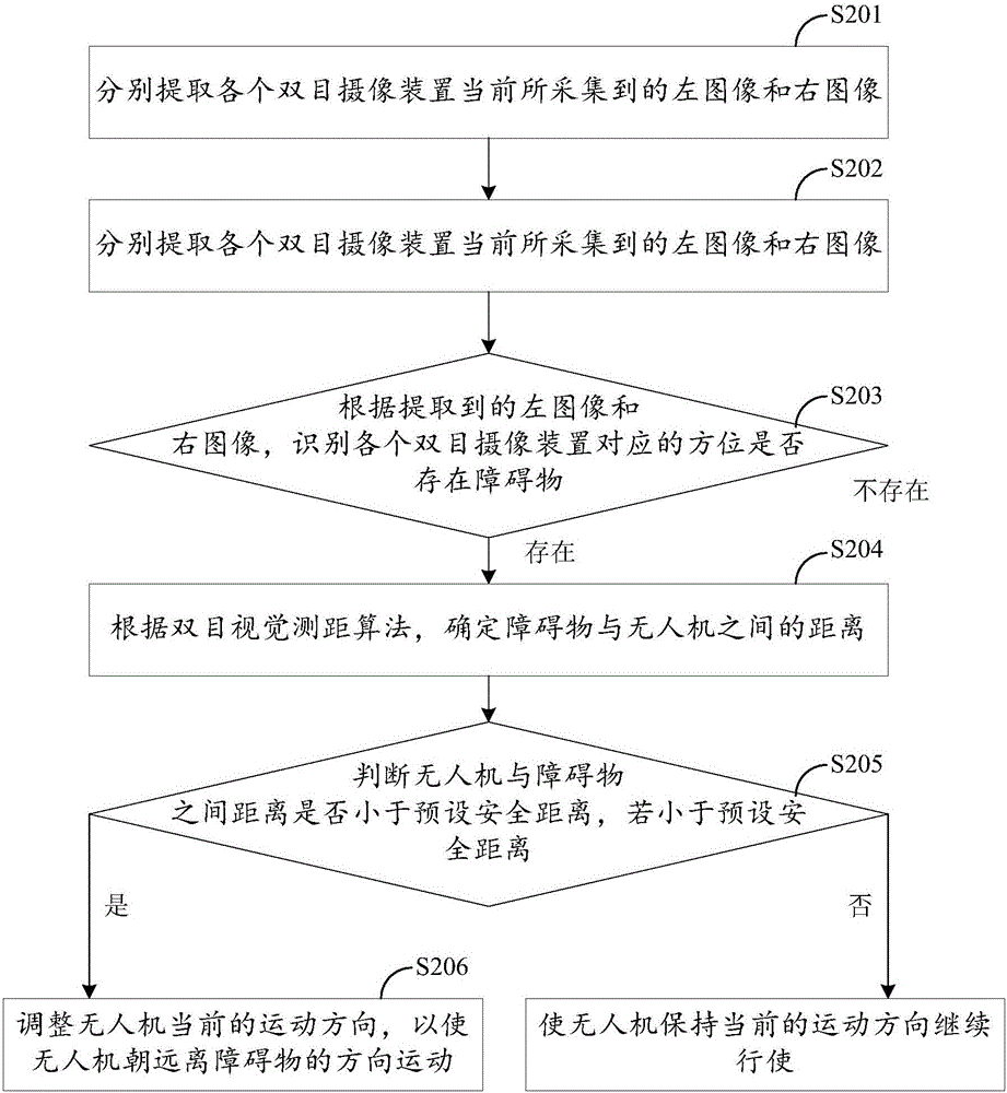
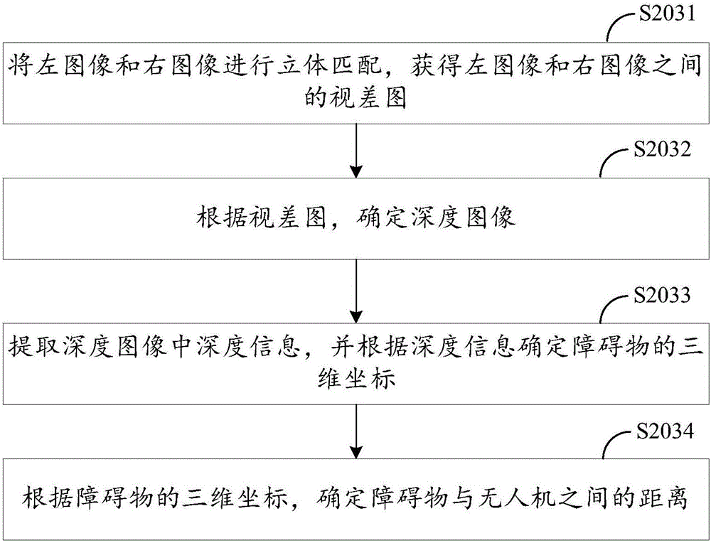
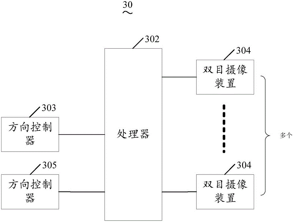
[0021] In order to realize the all-round obstacle avoidance of the UAV based on binocular vision, it is necessary to set up binocular camera devices around the UAV, and define the corresponding position of each binocular camera device according to the position of the binocular camera device on the UAV. Orientation, in this embodiment, preferably, binocular camera devices are arranged around the UAV to set at least one binocular camera at the front end, rear end, left side, right side, lower part and upper part of the UAV. camera device, and all binocular camera devices shoot in real time, and the binocular camera device on each side collects the left and right images of the space environment on one side of the drone. In this embodiment, preferably, the binocular camera device can be directly combined with two cameras, and the binocular camera device c...
PUM
 Abstract
Description
Claims
Application Information