Sensitivity testing equipment for a smoke alarm

A technology for smoke alarms and detection equipment, which can be applied to alarms, instruments, etc., can solve the problems of low detection efficiency, controlled smoke concentration, and difficulty in realizing smoke environment.

Active Publication Date: 2017-10-10
NINGBO KESAIDI ELECTRONICS TECH CO LTD
View PDF6 Cites 0 Cited by
  • Summary
  • Abstract
  • Description
  • Claims
  • Application Information

AI Technical Summary

Problems solved by technology

However, since the detection environment of the sensitivity of the smoke alarm is a smoke environment with a constant concentration, it is easy to achieve a constant smoke concentration in a closed environment, but it is difficult to control the smoke concentration in an open environment, and the smoke environment is difficult to achieve.
The sensitivity detection equipment of an existing smoke alarm closes the box to realize the smog environment of the alarm sensitivity detection. When the test is completed, the product is put into the closed box, and the product is taken out after the test is completed. However, the smog environment error of the sensitivity detection equipment is relatively large, the sensitivity detection accuracy is low, and the product is picked and placed manually, which has poor operability and detection efficiency. also lower

Method used


Image

  • Sensitivity testing equipment for a smoke alarm
  • Sensitivity testing equipment for a smoke alarm
  • Sensitivity testing equipment for a smoke alarm

Examples


Embodiment 1

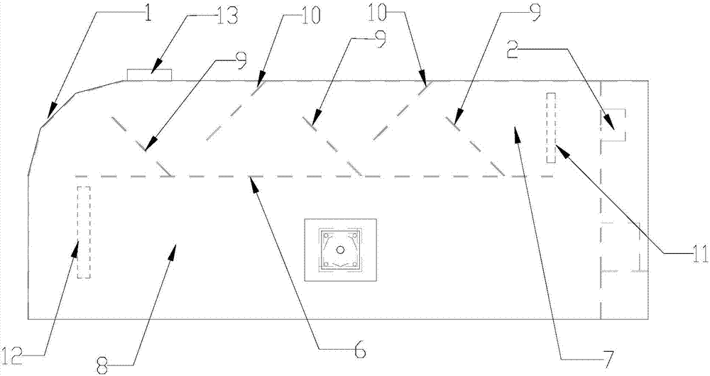
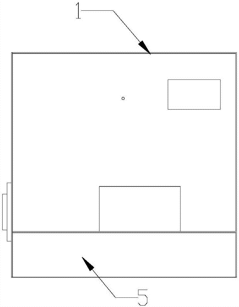
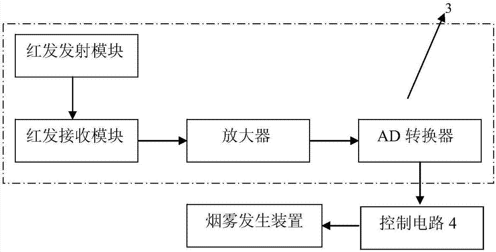
[0025] Embodiment 1: As shown in the figure, a sensitivity detection device for a smoke alarm includes a housing 1 with an open lower end, a smoke generating device 2, a concentration detection circuit 3, a control circuit 4 and a blowing device, a concentration detection circuit 3 and a control circuit. The circuit 4 is connected, the control circuit 4 is connected with the blowing device, and the control circuit 4 is provided with a concentration reference value range; the casing 1 is installed on the assembly line, and the assembly line closes the lower end opening of the casing 1, and at this time, a closed cavity is formed in the casing 1. Smoke chamber; the lower front end of the housing 1 is provided with an inlet, the lower rear end of the housing 1 is provided with an outlet, the inlet is provided with a first elastic door 5, and the outlet is provided with a second elastic door (not shown), the smoke The generating device 2 is arranged at the rear of the smoke chamber...

Embodiment 2

[0030] Embodiment 2: As shown in the figure, a sensitivity detection device for a smoke alarm includes a housing 1 with an open lower end, a smoke generating device 2, a concentration detection circuit 3, a control circuit 4 and a blowing device, a concentration detection circuit 3 and a control circuit. The circuit 4 is connected, the control circuit 4 is connected with the blowing device, and the control circuit 4 is provided with a concentration reference value range; the casing 1 is installed on the assembly line, and the assembly line closes the lower end opening of the casing 1, and at this time, a closed cavity is formed in the casing 1. Smoke chamber; the lower front end of the housing 1 is provided with an inlet, the lower rear end of the housing 1 is provided with an outlet, the inlet is provided with a first elastic door 5, and the outlet is provided with a second elastic door (not shown), the smoke The generating device 2 is arranged at the rear of the smoke chamber...

Embodiment 3

[0036] Embodiment 3: As shown in the figure, a sensitivity detection device for a smoke alarm includes a housing 1 with an open lower end, a smoke generating device 2, a concentration detection circuit 3, a control circuit 4 and a blowing device, a concentration detection circuit 3 and a control circuit. The circuit 4 is connected, the control circuit 4 is connected with the blowing device, and the control circuit 4 is provided with a concentration reference value range; the casing 1 is installed on the assembly line, and the assembly line closes the lower end opening of the casing 1, and at this time, a closed cavity is formed in the casing 1. Smoke chamber; the lower front end of the housing 1 is provided with an inlet, the lower rear end of the housing 1 is provided with an outlet, the inlet is provided with a first elastic door 5, and the outlet is provided with a second elastic door (not shown), the smoke The generating device 2 is arranged at the rear of the smoke chamber...


PUM


Abstract

The invention discloses a smoke alarm sensitivity detection device, comprising a case body whose lower end is provided with an opening, a smog generating device, a concentration detection circuit, a control circuit and a blowing device. The concentration detection circuit is connected to the control circuit; the control circuit is connected with the blowing device; the control circuit is provided with a concentration reference range; the case body is mounted on an assembly line which seals the lower end opening of the case body, and a sealed smog chamber is formed in the case body; a lower part of a front end of the case body is provided with an entrance where a first flexible door is arranged, and a lower part of a rear end of the case body is provided with an exit where a second flexible door is arranged; the smog generating device is arranged at the rear part of the smog chamber; the case body is provided with a separator plate therein; a distance is kept between the front end of the separator plate and the case body; a distance is kept between the rear part of the separator plate and the smog generating device; an upper flue is formed between the separator plate and the top of the case body; a lower flue is formed between the separator plate and the assembly line. The detection device has advantages such as high detection precision, strong operability and high detection efficiency.

Description

technical field [0001] The invention relates to a sensitivity detection device, in particular to a sensitivity detection device of a smoke alarm. Background technique [0002] Sensitivity is an important technical indicator of smoke alarms, and the sensitivity of smoke alarms directly determines the quality of smoke alarms. When smoke alarm manufacturers produce smoke alarms, it is necessary to test the sensitivity of each smoke alarm. However, since the detection environment of the sensitivity of the smoke alarm is a smoke environment with a constant concentration, it is easy to achieve a constant smoke concentration in a closed environment, but it is difficult to control the smoke concentration in an open environment, and the smoke environment is difficult to achieve. The sensitivity detection equipment of an existing smoke alarm closes the box to realize the smog environment of the alarm sensitivity detection. When the test is completed, the product is put into the clos...

Claims


Application Information

Patent Timeline
Patent Type & Authority Patents(China)
IPC IPC(8): G08B29/14
CPCG08B29/145
Inventor 蔡忠宝
Owner NINGBO KESAIDI ELECTRONICS TECH CO LTD
Why Eureka
Try Eureka