
A battery uniform glue injection equipment

A glue injection and uniform technology, applied in the field of uniform glue injection equipment for batteries, can solve the problems of slow concentrated diffusion of colloid, affecting the sealing performance of batteries, and easy clogging of injection devices, achieving good glue injection effect, avoiding wire drawing phenomenon, and sealing. Good results

Active Publication Date: 2017-12-22
ZHEJIANG YUNBANG BATTERY CO LTD
View PDF6 Cites 0 Cited by
  • Summary
  • Abstract
  • Description
  • Claims
  • Application Information

AI Technical Summary

Problems solved by technology

[0009] One of the purposes of the present invention is to address the deficiencies of the prior art, to overcome the glue injection process of the battery, the colloid is largely affected by the external environment, which makes the flow worse and then affects the sealing of the battery, and the glue injection process is slow. The colloid is too concentrated and diffuses slowly, which leads to poor sealing around and easy blockage of the injection device. A battery glue injection device with rapid injection, uniform distribution of colloid injection, and anti-clogging of the glue injection components is provided.

Method used


Image

  • A battery uniform glue injection equipment
  • A battery uniform glue injection equipment
  • A battery uniform glue injection equipment

Examples


Embodiment 1

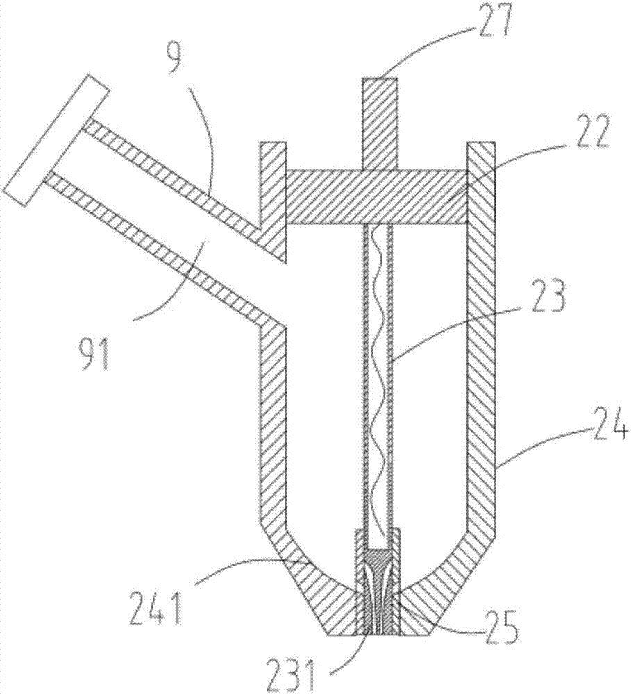
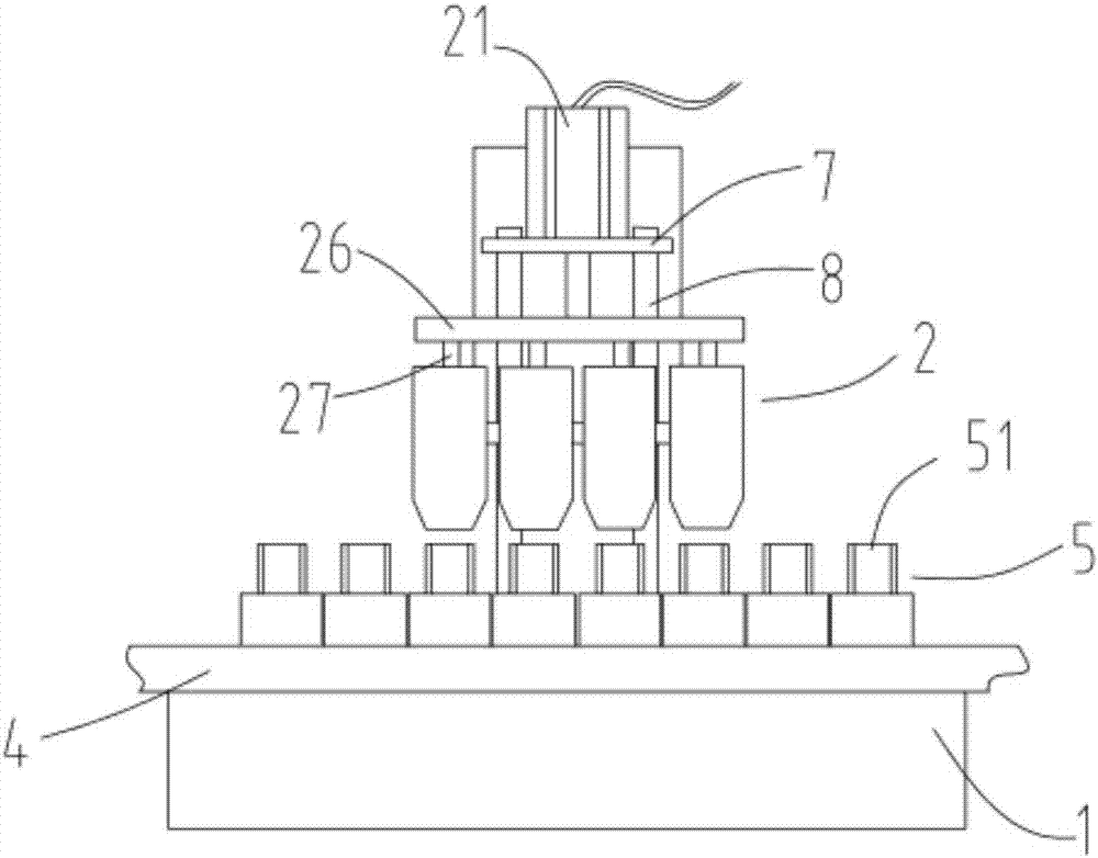
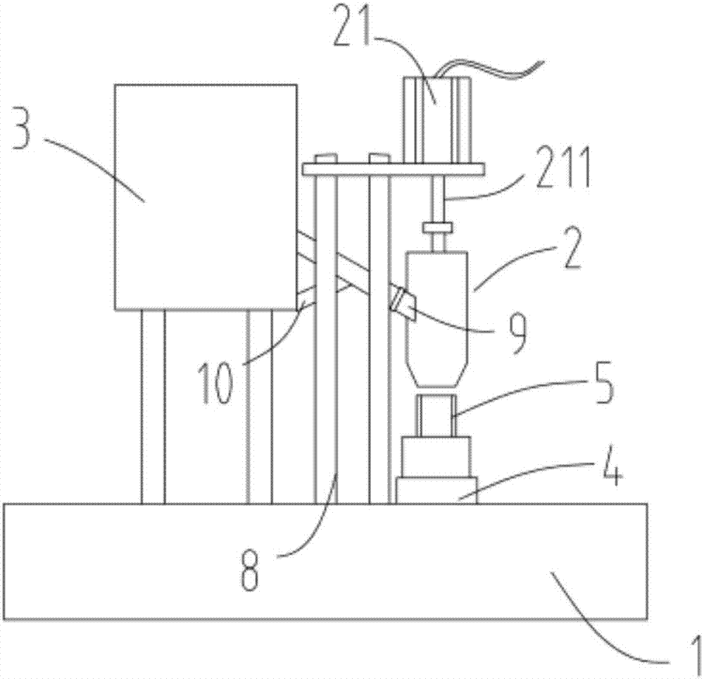
[0039] figure 1 It is a schematic diagram of the partial structure of the glue injection component of a battery uniform glue injection equipment, figure 2 It is a schematic diagram of the front structure of a battery uniform glue injection equipment, image 3 It is a side-view structural schematic diagram of a battery uniform glue injection equipment, Figure 4 It is a schematic cross-sectional view of the end of the discharge rod and the guide column of a battery uniform glue injection equipment, Figure 5 It is a structural schematic diagram of the end of the discharge rod of a battery uniform glue injection equipment, Figure 6 It is a structural schematic diagram of a material tank of a battery uniform glue injection equipment. Such as figure 1 , figure 2 , image 3 , Figure 4 , Figure 5 and Figure 6As shown, a battery uniform glue injection equipment, including a carrier table 1, a number of glue injection components 2 arranged in parallel at equal intervals...


PUM


Abstract

The invention relates to a battery uniform glue injection equipment, which includes a bearing table, several glue injection components arranged in parallel at equal intervals, a material tank for storing the glue, and an incoming component carrying several battery steel shells, the glue injection component and the battery steel The glue injection opening of the shell corresponds vertically; the glue injection assembly includes a power part, a pressure plate, a discharge rod, a glue injection barrel, and a material guide column; the pressure plate is set on the ejector rod of the power part; the discharge rod is set on the pressure plate; the material guide The column sleeve is set at the end of the discharge rod, and the discharge rod slides up and down relative to the inner wall of the guide column; the guide column is fixed on the glue injection barrel; the end of the discharge rod is provided with a semi-circular material guide hole; The material column is provided with a discharge hole; the invention overcomes the problem that during the battery glue injection process, the colloid is largely affected by the external environment, which makes the flow worse and then affects the sealing of the battery, the glue injection process is slow, the colloid injection is unevenly distributed, and The injection device is prone to clogging.

Description

technical field [0001] The invention relates to the technical field of dry battery production, in particular to a battery uniform glue injection equipment. Background technique [0002] With the advancement of battery technology, the production technology of alkaline batteries is becoming more and more mature, and the market demand is large. In some battery production lines, due to the relatively large volume of some batteries, it is relatively difficult to curl the head of the sealing end of the rolling paper inside. It is difficult to ensure that the sealing end of each battery steel case can be ironed firmly. If there is a gap in the seal of the diaphragm paper, the electrolyte will seep out after the electrolyte is injected, which will cause the battery to climb alkali, gas, and even cause the battery to explode, which is extremely dangerous. Therefore, a glue injection process needs to be added after the diaphragm paper is inserted. [0003] The Chinese patent with a...

Claims


Application Information

Patent Timeline
Patent Type & Authority Patents(China)
IPC IPC(8): H01M6/00H01M6/06H01M2/08H01M50/186
CPCH01M6/005H01M6/06H01M50/183
Inventor 丁丞
Owner ZHEJIANG YUNBANG BATTERY CO LTD
Learn More