Mobile terminal and imaging method
A technology of a mobile terminal and an imaging method, which is applied in the directions of image communication, TV, and color TV components, etc., can solve the problem of inconvenience for users to take panoramic pictures.
- Summary
- Abstract
- Description
- Claims
- Application Information
AI Technical Summary
Problems solved by technology
Method used
Image
Examples
Embodiment 1
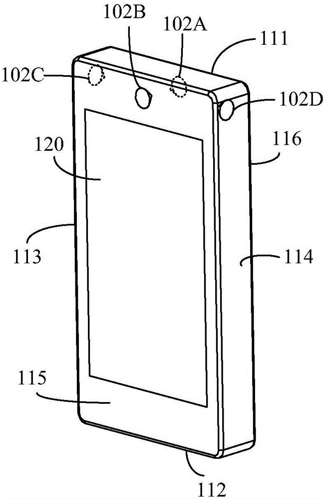
[0020] This embodiment provides a mobile terminal. Such as Figure 1A Shown is a schematic structural diagram of a mobile terminal according to this embodiment.
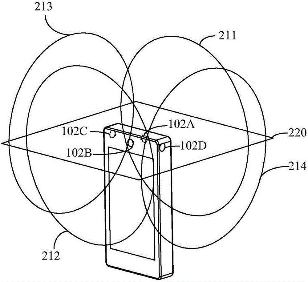
[0021] The mobile terminal of this embodiment includes a terminal body 101 and a plurality of cameras, wherein the plurality of cameras are all arranged on the terminal body 101, and the imaging central axis of each camera is located in the same target plane, and the controller (not shown in the figure) can A panorama picture is synthesized based on images captured simultaneously by multiple cameras 101 .
[0022] In this embodiment, the terminal body 101 has six sides. When the user holds the mobile terminal and faces the screen 120 to the user, they are the upper side 111, the lower side 112, the left side 113, the right side 114, The front 115 and the rear 116 , the sides described in the following embodiments are based on the user holding the mobile terminal and facing the screen to the user, and the side facing...
Embodiment 2
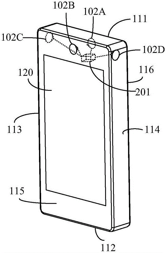
[0030] This embodiment makes further supplementary descriptions on the mobile terminal in Embodiment 1. The mobile terminal in this embodiment further includes a controller 201, which can control each camera.
[0031] Such as figure 2 As shown, the mobile terminal in this embodiment further includes a controller 201, and the controller 201 controls the shooting time and / or shooting sequence of each camera.
[0032] The controller 201 of this embodiment can be arranged on the circuit board inside the terminal body 101, and the controller 201 is electrically connected to each camera, and can control the shooting sequence and shooting time of each camera respectively. For example, the controller 201 is connected to the cameras 102A, 102B, 102C and 102D respectively. Trigger each camera to shoot at the same time, or trigger a certain camera to shoot, for example, only trigger camera 102C to shoot, or trigger camera 102A and camera 102B to shoot sequentially. It should be unders...
Embodiment 3
[0037]This embodiment provides an imaging method for a mobile terminal based on the above embodiments, where the execution body is an imaging device of the mobile terminal, and the imaging device may be set inside the mobile terminal, such as the controller described in the above embodiments. The structure of the mobile terminal in this embodiment is the same as that in the foregoing embodiments, and will not be repeated here.
[0038] Such as image 3 As shown, it is a schematic flow chart of the imaging method of the mobile terminal according to this embodiment. The imaging method of this embodiment includes:
[0039] Step 301, triggering a target camera in each camera to perform a shooting operation.
[0040] The target cameras may be all cameras, or some cameras, for example, the number of target cameras is 1, 2 or 3. Specifically, the imaging device may send a shooting instruction to the target camera, and the shooting instruction may include shooting time, and may also...
PUM
 Abstract
Description
Claims
Application Information
 - R&D
- Intellectual Property
- Life Sciences
- Materials
- Tech Scout
- Unparalleled Data Quality
- Higher Quality Content
- 60% Fewer Hallucinations
Browse by: Latest US Patents, China's latest patents, Technical Efficacy Thesaurus, Application Domain, Technology Topic, Popular Technical Reports.
© 2025 PatSnap. All rights reserved.Legal|Privacy policy|Modern Slavery Act Transparency Statement|Sitemap|About US| Contact US: help@patsnap.com


