Supercharge Your Innovation With Domain-Expert AI Agents!

Conveyor rollers and conveying equipment with moisture protection

A technology of conveying equipment and conveying rollers, which is applied in the direction of conveyors, conveyor objects, transportation and packaging, etc. It can solve the problems of equipment control system rust, corrosion, influence, etc., and achieve the effect of ensuring trouble-free operation

Active Publication Date: 2018-06-08
TGW MECHANICS GMBH
View PDF6 Cites 0 Cited by
  • Summary
  • Abstract
  • Description
  • Claims
  • Application Information

AI Technical Summary

Problems solved by technology

The problem faced in the use of conveying rollers or conveying equipment is that these conveying rollers or conveying equipment are subjected to dirt and dripping liquid
The result can be short-term damage such as short circuits and malfunctions of the plant control system as well as long-term damage in the form of, for example, rust, corroded contacts and the like

Method used


Image

  • Conveyor rollers and conveying equipment with moisture protection
  • Conveyor rollers and conveying equipment with moisture protection
  • Conveyor rollers and conveying equipment with moisture protection

Examples


Embodiment Construction

[0025] As an introduction, it should first be stated that in the various embodiments described in the different descriptions, the same components are provided with the same reference symbols or the same component designations, wherein the disclosure content contained in all the descriptions can be transferred according to the meaning to the same parts provided with the same reference numbers or the same component names. Moreover, the orientation descriptions selected in the specification, such as up, down, side, etc., are relative to the direct description and the drawings shown, and when the orientation changes, they can be transferred to the new orientation according to the meaning . In addition, individual features or combinations of features from the various exemplary embodiments shown and described can also form their own independent, inventive or inventive solutions.

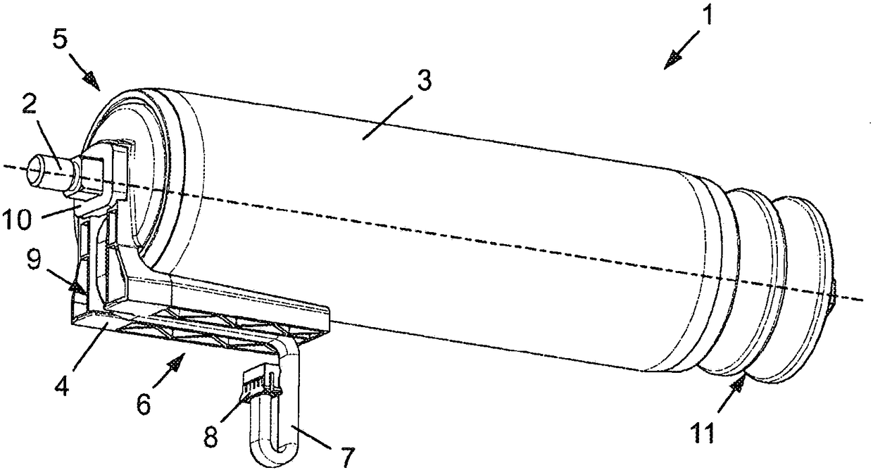
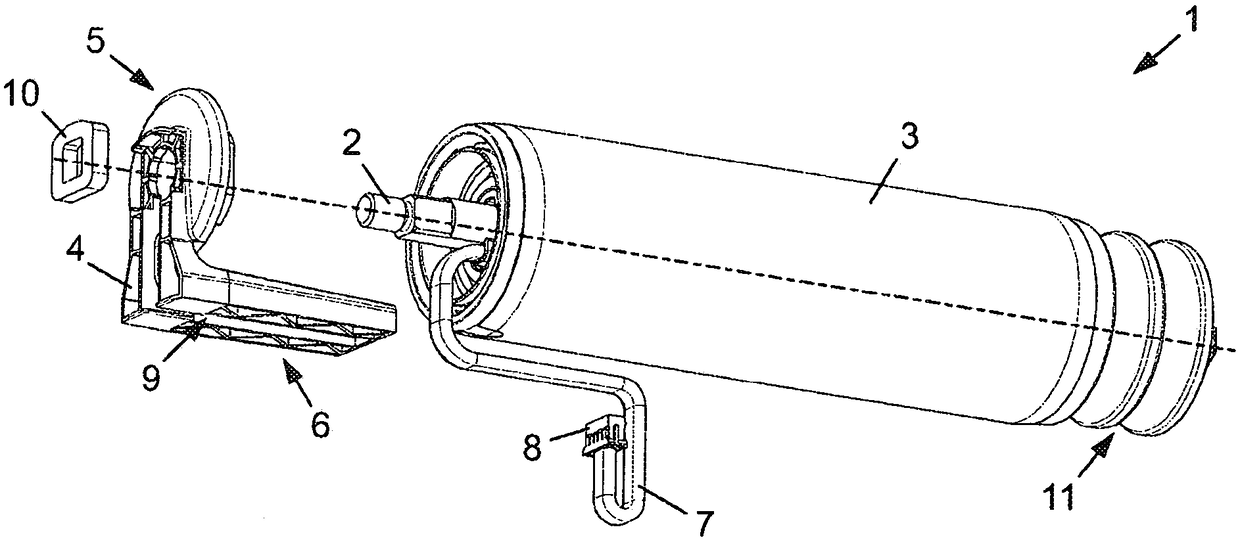
[0026] figure 1 and 2 Shown is an oblique view of an exemplary conveyor roller 1 ( figure 1 ) and e...


PUM


Abstract

Disclosed is a conveyor roller (1) which comprises a shaft (2), a roller body (3) which is mounted such that it can be rotated about the shaft (2), and a protective cap (4). The protective cap (4) has a disk-shaped first section (5) for covering the interior of the roller body (3), which is arranged fixedly with respect to the shaft (2) and is oriented normally with respect thereto, and a channel-like or roof-like second section (6) which is arranged obliquely with respect to the shaft (2) and runs over a part length of the roller body (3) such that it is spaced apart radially from the latter. Furthermore, a conveyor system (12) with a conveyor roller (1) is disclosed, in which conveyor system a connecting cable (7) of the conveyor roller (1) is run in a curve or a loop to an electrical interface (8, 17) with a connector box (15) of the conveyor system (12), wherein the lowest point of the curve / the loop is located below said interface (8, 17).

Description

technical field [0001] The invention relates to a conveyor roller having a shaft and a roller body rotatably supported about the shaft, a motor arranged in the roller body for driving the roller body and a protective cover comprising a cover for covering the roller body An inner disk-shaped first section and a roof-shaped second section, the first section being fixedly arranged relative to the axis and oriented perpendicularly to this axis. Furthermore, the invention relates to a conveying device comprising a conveying roller having a shaft, a roller body mounted rotatably about the shaft, a motor arranged in the roller body for driving the roller body, a protective cover And the connecting cable drawn out from the roller body and electrically connected with the motor. Furthermore, the conveying device comprises: two frame profiles extending at a distance, between which the conveying roller is arranged; power supply and / or data lines running along one frame profile and wiring...

Claims


Application Information

Patent Timeline
Patent Type & Authority Patents(China)
IPC IPC(8): B65G23/08B65G39/09B65G13/06B65G13/11
CPCB65G39/09B65G13/06B65G13/11B65G23/08
Inventor J·赖施尔
Owner TGW MECHANICS GMBH
Features
  • R&D
  • Intellectual Property
  • Life Sciences
  • Materials
  • Tech Scout
  • Unparalleled Data Quality
  • Higher Quality Content
  • 60% Fewer Hallucinations
Learn More