Check patentability & draft patents in minutes with Patsnap Eureka AI!

Switching tube driving circuit and refined reactive power compensation device

A driving circuit and compensation device technology, applied in reactive power compensation, reactive power adjustment/elimination/compensation, output power conversion devices, etc., can solve the problems of poor compensation effect, etc. The effect of improving reliability

Active Publication Date: 2021-06-18
HEBEI VAUBAN POWER TECH
View PDF3 Cites 0 Cited by
  • Summary
  • Abstract
  • Description
  • Claims
  • Application Information

AI Technical Summary

Problems solved by technology

[0006] The present invention proposes a switching tube drive circuit and a refined reactive power compensation device, which solves the problem of poor compensation effect of the reactive power compensation device in the prior art

Method used


Image

  • Switching tube driving circuit and refined reactive power compensation device
  • Switching tube driving circuit and refined reactive power compensation device
  • Switching tube driving circuit and refined reactive power compensation device

Examples


Embodiment Construction

[0061] The technical solutions in the embodiments of the present invention will be clearly and completely described below in conjunction with the embodiments of the present invention. Apparently, the described embodiments are only some of the embodiments of the present invention, not all of them. Based on the embodiments of the present invention, all other embodiments obtained by persons of ordinary skill in the art without creative efforts fall within the protection scope of the present invention.

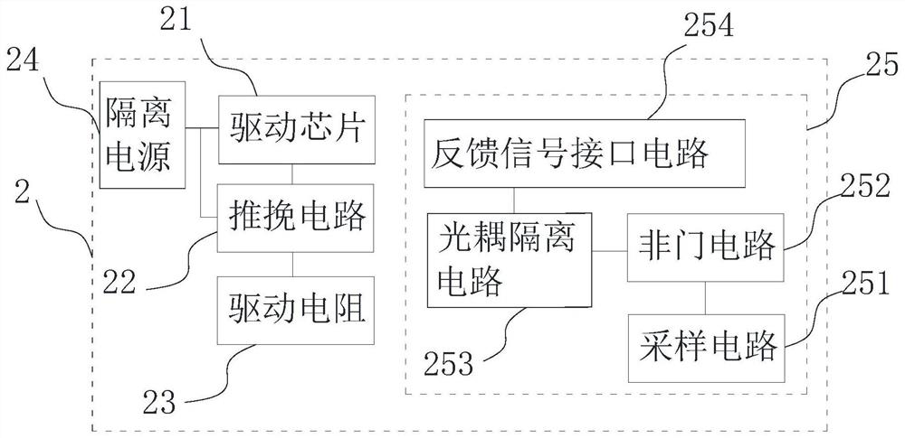
[0062] The switching tube drive circuit is twelve circuits with the same structure, which are divided into three groups, corresponding to the three-phase output of the power circuit 6 respectively, one of which is as figure 2 As shown, it includes a driver chip 21 , a push-pull circuit 22 and a driver resistor 23 connected in sequence, the driver chip 21 is used to connect to the control circuit 1 , and the driver resistor 23 is used to connect to the G pole of the switch tube 61 ...


PUM


Abstract

The invention belongs to the technical field of electronic conversion, and provides a switching tube driving circuit and a refined reactive power compensation device, the switching tube driving circuit comprises a driving chip, a push-pull circuit and a driving resistor which are connected in sequence, the driving chip is used for being connected with a control circuit, and the driving resistor is used for being connected with a G pole of a switching tube; and also comprises an isolated power supply, wherein the driving chip is an isolated driving chip, and the driving chip and the push-pull circuit are both connected with the isolated power supply; the driving resistor comprise an eighth resistor, a ninth resistor, a sixty-second resistor and a sixty-third resistor. According to the technical scheme, the problem of poor compensation effect of the reactive power compensation device in the prior art is solved.

Description

technical field [0001] The invention belongs to the technical field of electronic conversion, and relates to a switch tube drive circuit and a refined reactive power compensation device. Background technique [0002] The existing low-voltage reactive power compensation products are mainly divided into the following three categories: [0003] 1. Step compensation: The most common design scheme is to use several capacitors with the same capacity. At this time, the stepping step is the capacity of a single capacitor. Calculated according to the marked value, if the total compensation amount is 1, then the stepping step is the reciprocal of the number of capacitors. For example: if ten 20Kvar capacitors are installed in a compensation device, the total compensation amount is 200Kvar, and the stepping step is 20Kvar. Calculated by per unit value, the stepping step is 1 / 10. This design scheme is relatively simple, and it is also relatively easy to make the capacitor cycle switc...

Claims


Application Information

Patent Timeline
Patent Type & Authority Applications(China)
IPC IPC(8): H02M1/08H02M1/088H02J3/18
CPCH02M1/08H02M1/088H02J3/18Y02E40/30Y02E40/10
Inventor 马洪亮任俊辉
Owner HEBEI VAUBAN POWER TECH
Features
  • R&D
  • Intellectual Property
  • Life Sciences
  • Materials
  • Tech Scout
  • Unparalleled Data Quality
  • Higher Quality Content
  • 60% Fewer Hallucinations
Learn More