Single-optical fiber scanning micro device as well as production method and control method thereof
A control method and micro-device technology, applied in the field of optical scanning, can solve problems such as difficult processing, and achieve the effect of reducing calculation time
- Summary
- Abstract
- Description
- Claims
- Application Information
AI Technical Summary
Problems solved by technology
Method used
Image
Examples
Embodiment 1
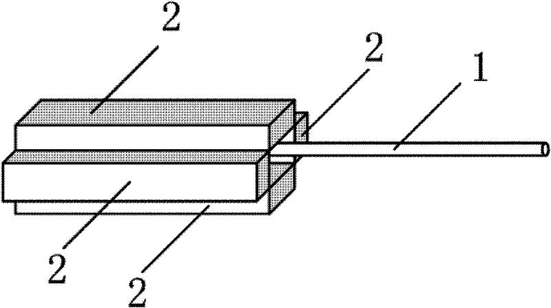
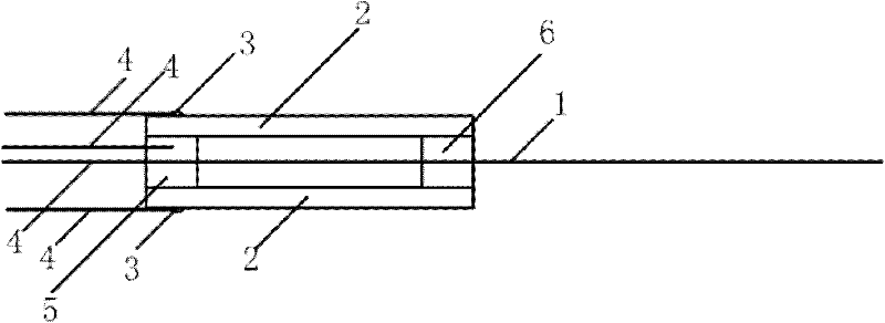
[0053] Embodiment 1: Fabrication of single-fiber scanning micro-device
[0054] In this example, the materials used to make the single-fiber scanning micro-device are: four thin ceramic strips, single-mode optical fiber, conductive glue, superglue, and five thin wires.
[0055] 1. Take four piezoelectric ceramic sheets with a length of 8 mm, a width of 1.2 mm, and a thickness of 0.5 mm, coated with silver electrode layers on both sides;
[0056] 2. Remove the 15mm coating from the end of a single-mode optical fiber to expose the bare optical fiber, cut the end face of the optical fiber flat with a fiber cutter, place the optical fiber in the gap between two piezoelectric ceramic sheets, and reserve a length of 10mm (the resonance frequency is about 1kHz) as the vibration free end;
[0057] 3. Four pieces of ceramics surround the cavity, and the two opposite piezoelectric ceramics have the same polarization direction. Place the optical fiber and a wire on the axis of the cera...
Embodiment 2
[0059] Embodiment 2: Finite element analysis of single-fiber scanning micro-device
[0060] Such as Figure 5 , 6 As shown in , 7 and 8, the structural dynamics analysis of the single-fiber scanning micro-device under the electromechanical coupling field is carried out by using the finite element method. The analysis results can predict and fully verify the dynamics of the micro-device during the scanning process with high precision. characteristic.
[0061] The finite element analysis of the single-fiber scanning micro-device realized in this embodiment includes:
[0062] Modal Analysis: Analyze the natural frequencies of a structure. Provides a reference for the applied drive signal frequency.
[0063] Harmonic response analysis: Obtain the scanning amplitude of the scanner under the sine wave driving signal of each frequency. The driving signal to be applied can be determined under different scanning requirements;
[0064] Transient analysis: It is possible to determi...
Embodiment 3
[0071] Embodiment 3: Voltage-driven control of single-fiber scanning micro-device
[0072] As shown in 9, 10, and 11, the probe is driven by two signals. The driving signal adopts a sine wave modulated by a sine wave, which can be scanned in a spiral mode. The carrier frequency is the natural frequency of the fiber cantilever, and the modulation wave frequency corresponds to the scanning frame rate. The phases of the modulated waves of the two signals are the same, and the carrier waves differ by 90°. If the ceramic pair performs simple harmonic vibration with the same frequency and the same amplitude with a difference of 90° in both horizontal and numerical directions, the fiber scanning trajectory is a circle. If the amplitude increases and decreases repeatedly at a certain frequency, a helical trajectory can be obtained. The modulated sine wave of 1 / 4 cycle corresponds to one frame of image (that is, a spiral signal from inside to outside) during scanning, that is, the m...
PUM
| Property | Measurement | Unit |
|---|---|---|
| radius | aaaaa | aaaaa |
Abstract
Description
Claims
Application Information
 - R&D
- Intellectual Property
- Life Sciences
- Materials
- Tech Scout
- Unparalleled Data Quality
- Higher Quality Content
- 60% Fewer Hallucinations
Browse by: Latest US Patents, China's latest patents, Technical Efficacy Thesaurus, Application Domain, Technology Topic, Popular Technical Reports.
© 2025 PatSnap. All rights reserved.Legal|Privacy policy|Modern Slavery Act Transparency Statement|Sitemap|About US| Contact US: help@patsnap.com


