Photoelectric-isolated high-power brushless direct-current motor drive device and drive feedback processing method

A brushed DC motor, photoelectric isolation technology, applied in the direction of single motor speed/torque control, electronic commutator, etc., can solve the problem of damage to the motor and main controller, little influence on the normal operation of the system, and interference with the normal operation of the drive control system and other problems to achieve the effect of improving stability and efficiency, improving electromagnetic interference and electromagnetic compatibility

Active Publication Date: 2015-12-09
NORTHWESTERN POLYTECHNICAL UNIV
View PDF3 Cites 1 Cited by
  • Summary
  • Abstract
  • Description
  • Claims
  • Application Information

AI Technical Summary

Problems solved by technology

At this time, the system has electromagnetic interference and electromagnetic compatibility problems, but these problems are not obvious when the system power is not large, and have little impact on the normal operation of the system
In the high-power brushless DC motor drive control system, if this scheme is still adopted, electromagnetic interference and electromagnetic compatibility problems will interfere with the normal operation of the drive control system and the weak current main controller, and will damage the motor and the main controller in severe cases.

Method used


Image

  • Photoelectric-isolated high-power brushless direct-current motor drive device and drive feedback processing method
  • Photoelectric-isolated high-power brushless direct-current motor drive device and drive feedback processing method
  • Photoelectric-isolated high-power brushless direct-current motor drive device and drive feedback processing method

Examples


Embodiment Construction

[0028] Now in conjunction with embodiment, accompanying drawing, the present invention will be further described:

[0029] This embodiment is used to drive a high-power brushless DC motor in a photoelectric isolation type, and the high-power brushless DC motor is used as an underwater vehicle propulsion actuator.

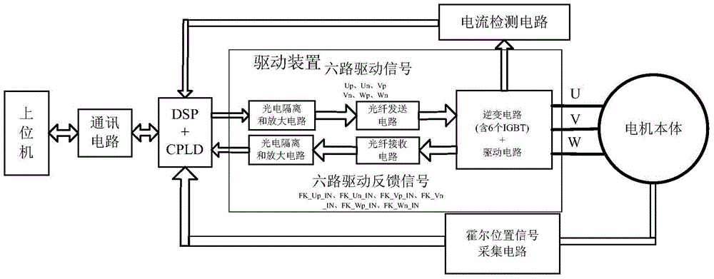
[0030] Refer to attached figure 1 , as can be seen from the figure, the brushless DC motor control system is composed of the upper computer, communication circuit, DSP+CPLD controller, inverter circuit, drive device, current detection circuit, Hall position signal acquisition circuit and motor body.

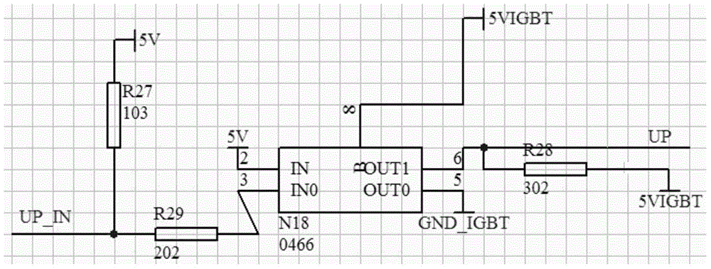
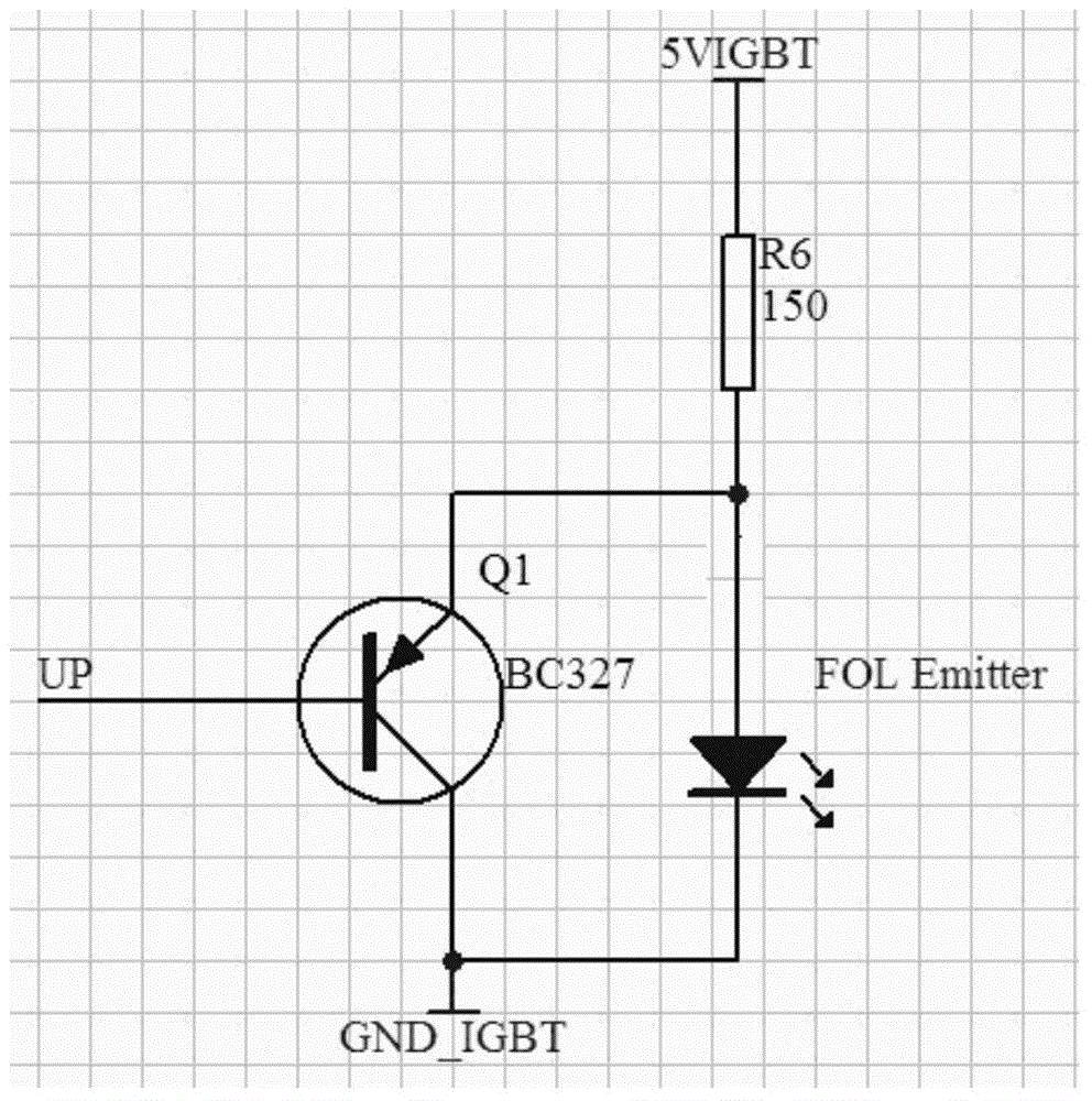
[0031] The drive device includes two drive signal photoelectric isolation and amplification circuits, an optical fiber transmission circuit, an optical fiber reception circuit and a drive circuit; the input end of the first drive signal photoelectric isolation and amplification circuit receives the 6 output signals of the commutation control DSP of the brushless DC mot...


PUM


Abstract

The invention relates to a photoelectric-isolated high-power brushless direct-current motor drive device and a drive feedback processing method. Six paths of drive signals UP-IN, UN-IN, VP-IN, VN-IN, WP-IN and WN-IN, which are output by a high-power brushless direct-current motor drive control system digital signal processor (DSP) and a complex programmable logic device (CPLD) controller through phase-change control, generate six paths of insulated gate bipolar translator (IGBT) drive signals UP, UN, VP, VN, WP and WN; the six paths of drive signals pass through an optical fiber transmission circuit, and achieve conversion of the IGBT drive signals from electric signals into optical signals; IGBT drive feedback signals FK-UP-IN, FK-UN-IN, FK-VP-IN, FK-VN-IN, FK-WP-IN and FK-WN-IN pass through an optical fiber receiving circuit and achieve conversion from the optical signals into the electric signals; the IGBT drive feedback signals are input into the CPLD; and whether the IGBT drive circuit normally works or not is judged by the drive feedback processing method. According to the photoelectric-isolated high-power brushless direct-current motor drive device and the drive feedback processing method, drive control of a high-power brushless direct-current motor is achieved; the problems of electromagnetic interference and electromagnetic compatibility of the traditional brushless direct-current motor drive control system are greatly improved; and the working stability and efficiency of the system are improved.

Description

technical field [0001] The invention belongs to the field of brushless DC motor drive control, and relates to a photoelectric isolation type high-power brushless DC motor drive device and a drive feedback processing method. Background technique [0002] High-power brushless DC motors have the advantages of high operating efficiency, good speed regulation performance, and high reliability, and are especially suitable for aviation, aerospace, navigation and other fields that have special requirements for system efficiency and reliability. [0003] The high-power brushless DC motor drive control system is a system where strong and weak currents coexist, and the high-frequency PWM modulation pulses it uses can easily cause great interference to weak current circuits outside the drive control system. This kind of electronically commutated motor has requirements for the drive control system to resist internal and external interference, so the electromagnetic interference and elect...

Claims


Application Information

Patent Timeline
Patent Type & Authority Applications(China)
IPC IPC(8): H02P6/08H02P6/16
Inventor 狄正飞张克涵陈冬季小尹阎龙斌胡欲立宋保维潘光严卫生刘明雍
Owner NORTHWESTERN POLYTECHNICAL UNIV
Why Eureka
Try Eureka