D.C. Voltage conversion electric appliance

A DC voltage, conversion circuit technology, applied in the direction of converting DC power input to DC power output, adjusting electrical variables, instruments, etc., can solve problems such as large power loss, switching loss, power loss in reverse recovery time, etc.

Inactive Publication Date: 2003-09-17
KOITO MFG CO LTD
View PDF0 Cites 2 Cited by
  • Summary
  • Abstract
  • Description
  • Claims
  • Application Information

AI Technical Summary

Problems solved by technology

[0006] First, when focusing on the power loss during the reverse recovery time of the rectifier diode provided on the secondary side of the transformer, the switching element is in the on state while the current flows into the diode, and the diode is in the reverse bias state. Power loss during recovery time
Also, the total amount of losses in the diode's reverse recovery time is proportional to the switching frequency, so in current continuous mode, the higher the frequency, the greater the power loss
[0007] In addition, when the switching element is turned on, the primary current of the transformer is generated, so the switching loss of the element occurs

Method used


Image

  • D.C. Voltage conversion electric appliance
  • D.C. Voltage conversion electric appliance
  • D.C. Voltage conversion electric appliance

Examples


Embodiment Construction

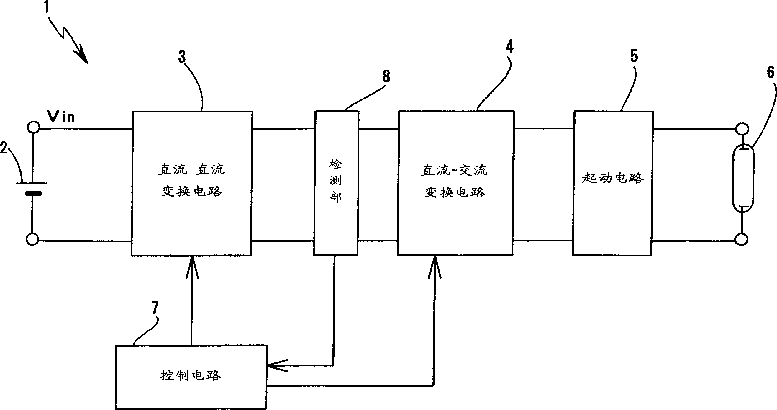
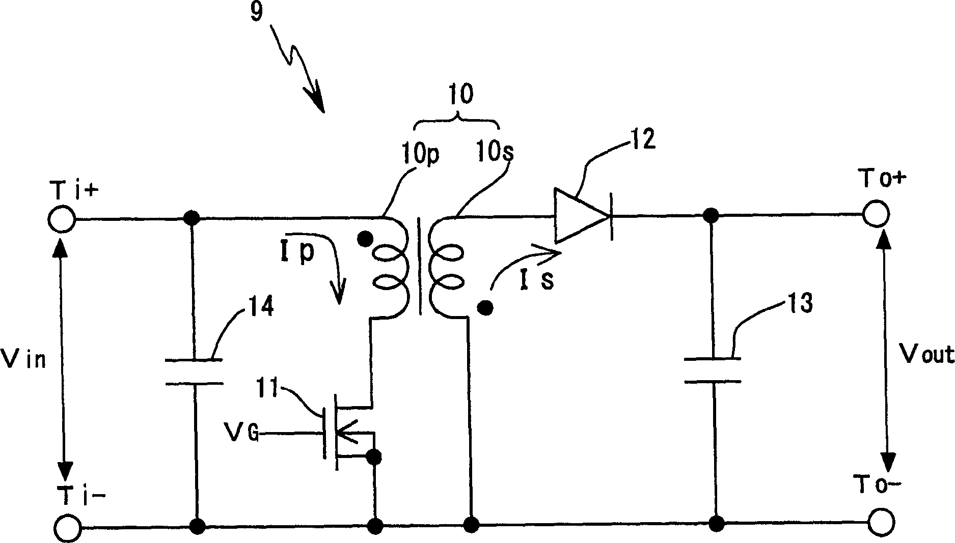
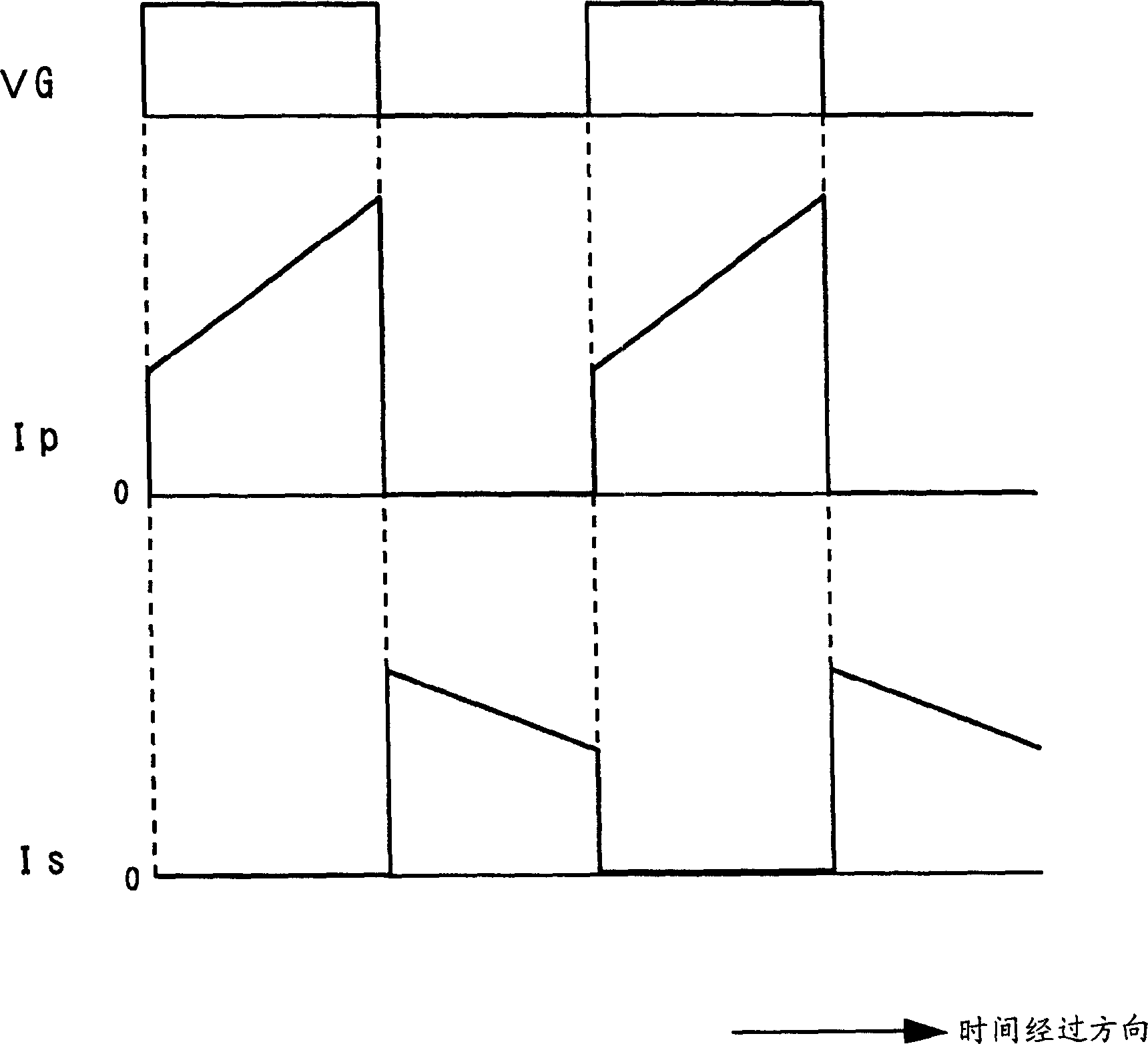
[0026] The DC voltage conversion circuit of the present invention has a feedback type circuit structure including a transformer and a switching element provided on the primary side of the transformer, the transformer stores energy when the switching element is in an on state, and the switching element is in an off state. This energy is output from the secondary winding. In the present invention, by performing the drive control of the current boundary mode described later, it is suitable for the improvement of electrical efficiency, the miniaturization of the circuit device, and the cost reduction. For example, it can be applied to a discharge lamp ignition circuit (especially as a vehicle lamp) In a discharge lamp such as a metal halide lamp as a light source, the ignition circuit when the installation space of the device including the ignition circuit is restricted), but is not limited thereto, and can be widely used in various applications such as power supply circuits.

[0...


PUM


Abstract

In the DC voltage conversion circuit of the feedback type structure, the switching frequency is increased in frequency and the electrical efficiency is improved at the same time. Control is carried out so that the switching element (11) provided in the primary side of the transformer (10) constituting the direct current voltage conversion circuit (15) becomes a conduction period, the transformer (10) stores energy, and the energy is stored during the off period of the switching element. The energy is output from the secondary winding (10s), and at the same time when the output of the energy from the secondary winding (10s) is completed, the switching element (11) is brought into a conduction state. Therefore, the time from when the secondary side current Is of the transformer (10) becomes zero to when the primary side Ip of the transformer starts to flow is detected, and the switching frequency is changed by the control unit (16), so that the time is shortened.

Description

technical field [0001] The invention relates to a technique for improving circuit efficiency and reducing cost in a feedback DC voltage conversion circuit. Background technique [0002] Various configurations are known for a DC voltage conversion circuit (so-called DC-DC converter) that converts a DC input voltage into a desired DC voltage. [0003] For example, in an application to an ignition circuit of a discharge lamp (metal halide lamp, etc.), a feedback type structure can be cited as a DC-DC conversion circuit for converting a DC input voltage from a DC power supply into a desired DC voltage. That is, a structure is provided in which a semiconductor switching element is connected to the primary winding side of a conversion transformer to perform on / off control of the element, and a rectifying diode and a smoothing capacitor are provided on the secondary side of the transformer. [0004] As far as the operation of the feedback type circuit is concerned, for example, in...

Claims


Application Information

Patent Timeline
Patent Type & Authority Applications(China)
IPC IPC(8): H02M3/28H02M3/335H05B41/288
CPCH02M3/33507H05B41/2886Y02B20/00
Inventor 市川知幸太田真司
Owner KOITO MFG CO LTD
Why Eureka
Try Eureka