
Screw and normal juice machine

A juicer and screw technology, applied in the field of food processing, can solve the problems of increasing the weight of the screw 1', poor user experience, waste of materials, etc., and achieve the effects of convenient assembly, reduced processing difficulty, and reliable connection

Inactive Publication Date: 2016-07-27
FOSHAN SHUNDE MIDEA ELECTRICAL HEATING APPLIANCES MFG CO LTD +1
View PDF7 Cites 5 Cited by
  • Summary
  • Abstract
  • Description
  • Claims
  • Application Information

AI Technical Summary

Problems solved by technology

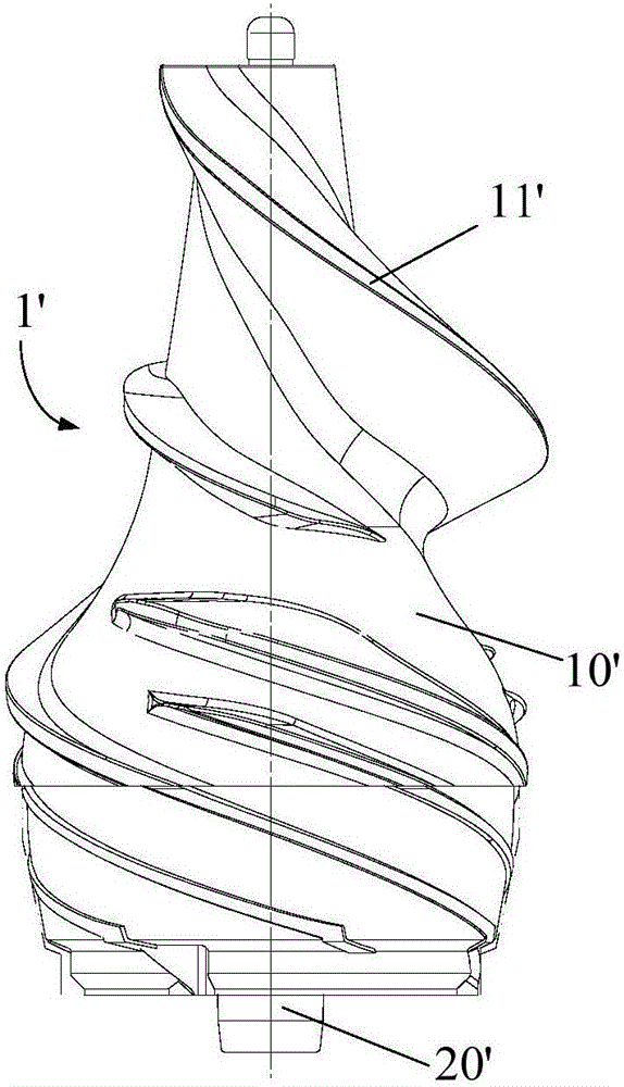
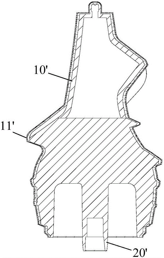
However, the existing hollow screw body 10' is still very heavy. On the one hand, it wastes materials, and on the other hand, it brings a bad user experience, especially the stainless steel screw. According to the characteristics of stainless steel materials, the stainless steel screw body 10 with a thickness of 2-3 mm 'It can fully meet the pressing needs of conventional fruits, but due to the limitation of the overall shape, the existing screw body 10' cannot be turned to remove more cumbersome parts, which increases the weight of the screw 1' in disguise

Method used


Image

  • Screw and normal juice machine
  • Screw and normal juice machine
  • Screw and normal juice machine

Examples


Embodiment 1

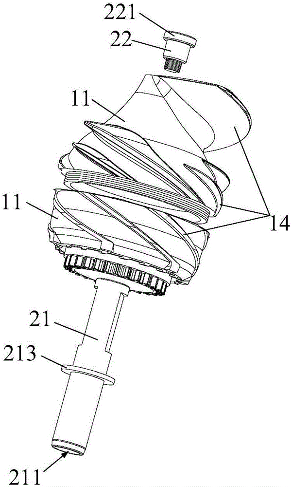
[0086] Such as Figure 3 to Figure 6 As shown, the screw 1 includes a housing 10 and a rotating shaft 20, the housing 10 is provided with a support seat 12, the upper end of the housing 10 is provided with a counterbore 13, the horizontal wall surface of the counterbore 13 is a limiting surface 131, and The vertical wall surface of the head hole 13 is provided with a limit groove 132 along the vertical direction, and the casing 10 is horizontally segmented to form two upper and lower sub-housings 11, and the lower interface end of the upper sub-housing 11 is provided with an external thread , the upper interface end of the lower sub-housing 11 is provided with an internal thread; the rotating shaft 20 includes a shaft body 21 and an axial locking member 22, the lower end of the shaft body 21 is provided with a shaft hole 211, and the upper end is provided with a threaded hole 212, and The side wall in the middle is provided with a support plate 213; the lower end of the axial ...

Embodiment 2

[0089] Such as Figure 7 to Figure 10 As shown, the screw rod 1 includes a housing 10, a rotating shaft 20 and two buckles 30 with threaded holes 212. The housing 10 is provided with a support seat 12, and the upper end of the housing 10 is provided with a countersunk hole 13, and the countersunk hole The horizontal wall surface of 13 is a limit surface 131, and the vertical wall surface of the counterbore 13 is provided with a limit groove 132 along the vertical direction, and the housing 10 is longitudinally divided into two left and right sub-housings 11, and the two sub-housings 11 The upper and lower ends of the shaft are provided with external threads; the rotating shaft 20 includes a shaft body 21 and an axial locking member 22, the lower end of the shaft body 21 is provided with a shaft hole 211, and the upper end is provided with a threaded hole 212, and the side wall in the middle A support plate 213 is provided, the lower end of the axial locking member 22 is provid...


PUM


Abstract

The invention provides a screw and a normal juice machine. The screw comprises a shell made of metal and a rotating shaft, wherein helical teeth are arranged on the peripheral wall of the shell; the rotating shaft is connected with the shell, and is capable of driving the shell to rotate; the shell comprises a plurality of sub shells, and the plurality of sub shells are spliced to form the shell. The screw provided by the invention comprises the rotating shaft and the shell, wherein the shell is formed by connecting the plurality of sub shells in a matched manner; the size of each sub shell is relatively small, therefore, the processing difficulty is greatly reduced, further, the redundant material on each sub shell can be conveniently removed through the turning process or other processes, and thus the wall thickness of each sub shell is reduced; the processed sub shells are connected together through combination to form the complete shell, thus the integral size of the shell is effectively reduced, and finally, the purpose of reducing the weight of the screw is achieved; meanwhile, the reduction of the size and the weight of the shell is also beneficial for the other secondary processing, and thus the processing difficulty of the screw is further reduced.

Description

technical field [0001] The invention relates to the technical field of food processing, in particular to a screw for a juicer and a juicer including the screw. Background technique [0002] The original juicer screw 1' mainly includes a rotating shaft 20' and a screw body 10' provided with helical teeth 11', as figure 1 and figure 2 shown. At present, among the existing juice machine screws 1', some are for reducing weight, and some are for filling some auxiliary materials in the screw main body 10', such as cold storage agent, to improve the taste of food, and some screw main bodies 10' are hollow. structure. However, the existing hollow screw body 10' is still very heavy. On the one hand, it wastes materials, and on the other hand, it brings a bad user experience, especially the stainless steel screw. According to the characteristics of stainless steel materials, the stainless steel screw body 10 with a thickness of 2-3 mm 'It can fully meet the pressing needs of conv...

Claims


Application Information

Patent Timeline
Patent Type & Authority Applications(China)
IPC IPC(8): A47J19/00
CPCA47J19/00
Inventor 房振潘典国曹达华
Owner FOSHAN SHUNDE MIDEA ELECTRICAL HEATING APPLIANCES MFG CO LTD
Learn More