
Automatic induction glue spraying device for brake shoe

A technology of automatic induction and brake shoes, applied in the direction of spraying devices, etc., can solve the problems affecting the next process, unevenness, low production efficiency, etc., and achieve the effect of strong operation stability

Inactive Publication Date: 2016-07-27
湖北新亿通机车配件有限公司
View PDF1 Cites 8 Cited by
  • Summary
  • Abstract
  • Description
  • Claims
  • Application Information

AI Technical Summary

Problems solved by technology

[0002] During the production process of the brake shoe, glue needs to be sprayed and dried on the outer curved surface, and then the brake pad is bonded to the glue sprayed place. In the existing process, the glue is usually sprayed on the brake shoe manually with an air pressure spray gun, not only The production efficiency is low, the cost is high, and the spraying position and spraying time cannot be grasped during manual spraying, which may easily cause uneven glue layer and directly affect the progress of the next process. A few automatic glue spraying equipment for brake shoes also have certain defects
[0003] For example, the invention patent of authorized notification number CN202778836U discloses a "glue spraying system for motorcycle brake shoes", including a conveying device, a glue spraying device and a drying device. The conveying device includes a frame and a conveyor belt installed on the frame; The glue spraying device includes a glue spraying room fixed on the frame. The surroundings of the glue spraying room are closed. The top of the glue spraying room is equipped with an exhaust device. The inside of the glue spraying room is provided with a linear track, which is located above the conveyor belt and The space is perpendicular to the conveyor belt, and a reciprocating machine is installed in the linear track, and a spray gun is installed on the reciprocating machine, and the nozzle of the spray gun is aimed at the upper surface of the conveyor belt; the glue spraying device generates a Z-shaped reciprocating motion track through the reciprocating machine set on the linear track For glue spraying, in actual production, due to the large back and forth movement of the zigzag track, when the conveyor belt moves a little faster, it is prone to missing spray and uneven glue spraying, which is unfavorable to the subsequent process

Method used


Image

  • Automatic induction glue spraying device for brake shoe
  • Automatic induction glue spraying device for brake shoe
  • Automatic induction glue spraying device for brake shoe

Examples


Embodiment Construction

[0025] In order to facilitate a better understanding of the purpose, structure, features, and effects of the present invention, the present invention will now be described in further detail in conjunction with the accompanying drawings and specific embodiments.

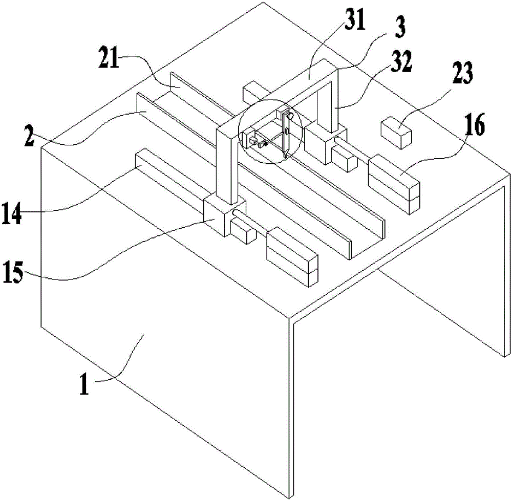
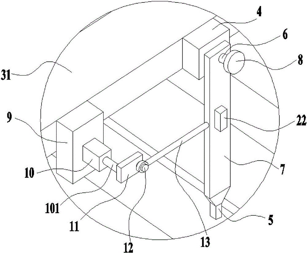
[0026] Brake shoe automatic induction glue spraying device among the present invention, as figure 1 and figure 2 As shown, the frame platform 1 is included, the frame platform 1 is provided with a guide rail 2, the guide rail 2 is composed of two baffle plates 21 arranged in parallel, a gantry 3 is arranged across the top of the guide rail, and one side of the top beam 31 of the gantry 3 A spray head fixing seat 4 is provided, and the spray head fixing seat 4 is provided with a rotating shaft 6 arranged along the direction of the guide rail. The rotating shaft 6 is provided with a glue spray head mounting plate 7, and the glue spray head 5 is arranged on the bottom of the glue spray head mounting plate 7. The glue s...


PUM


Abstract

The invention discloses an automatic induction glue spraying device for a brake shoe. The automatic induction glue spraying device comprises a rack platform. A guide rail is arranged on the rack platform. A portal frame is arranged above the guide rail in a spanning manner. A spraying head fixing seat is arranged on one side of a top beam of the portal frame. A glue spraying head capable of swinging back and forth in the direction perpendicular to the guide rail is arranged on the spraying head fixing seat. The portal frame is provided with a driving device used for driving the glue spraying head to swing back and forth in the direction perpendicular to the guide rail. Glue spraying can be conducted on the outer circumferential face of the brake shoe stably and evenly, the glue spraying head can move forwards and backwards in the direction of the guide rail, and the glue spraying position is convenient to adjust.

Description

technical field [0001] The invention relates to a glue spraying device, in particular to a brake shoe automatic induction glue spraying device. Background technique [0002] During the production process of the brake shoe, glue needs to be sprayed and dried on the outer curved surface, and then the brake pad is bonded to the glue sprayed place. In the existing process, the glue is usually sprayed on the brake shoe manually with an air pressure spray gun, not only The production efficiency is low, the cost is high, and the spraying position and spraying time cannot be grasped during manual spraying, which may easily cause uneven glue layer and directly affect the progress of the next process. A few automatic glue spraying equipment for brake shoes also have certain defects. [0003] For example, the invention patent of authorized notification number CN202778836U discloses a "glue spraying system for motorcycle brake shoes", including a conveying device, a glue spraying device...

Claims


Application Information

Patent Timeline
Patent Type & Authority Applications(China)
IPC IPC(8): B05B13/02B05B13/04B05B15/08B05B15/68
CPCB05B13/0278B05B13/0405B05B15/68
Inventor 阮开义
Owner 湖北新亿通机车配件有限公司
Learn More